By MedLinket Clinical Education Team | Updated: February 2026 | 15 min read
📚 This article is part of our Hospital Monitor Reading & Accessories Guide series.
⚡ Quick Answer: Hospital patient monitor alarms indicate changes in vital signs that need attention. Red alarms (continuous tone) are life-threatening and require immediate response. Yellow alarms (intermittent tone) need prompt assessment within minutes. Blue/white alarms (single beep) signal equipment or technical issues. The most critical rule: always assess the patient first, then check the monitor. Between 85% and 99% of hospital alarms are false or clinically insignificant — but every alarm must be taken seriously until verified.
If you are hearing a monitor beep in a hospital room, it does not always mean the patient is in immediate danger. Many alarms are triggered by loose sensors, movement, temporary threshold changes, or measurement issues. Staff should still assess the patient first, but monitor alarms are often a prompt to check both the patient and the equipment.
🔑 Key Takeaways
-
Hospital alarms are tiered by severity: red (critical), yellow (warning), and blue/white (advisory) — each requiring a different response speed.
-
The overwhelming majority of patient monitor alarms are false or non-actionable, but every alarm must be verified by assessing the patient first.
-
SpO₂, heart rate, blood pressure, and ECG each trigger specific alarm types with distinct causes and responses.
-
Alarm fatigue is a documented safety hazard — reducing false alarms through proper skin prep, quality monitoring accessories, and patient-specific alarm settings is a shared clinical responsibility.
-
Quality ECG cables, SpO₂ sensors, and NIBP cuffs directly reduce false alarms and improve patient safety outcomes.
📖 In This Article
Alarm Priority Levels: Red, Yellow, and Blue
Every modern patient monitor — whether from Philips, GE Healthcare, Mindray, Dräger, or another manufacturer — uses a tiered alarm system. Understanding these tiers is the first step to responding correctly. While specific alarm tones and display styles differ between brands, the fundamental priority structure follows the IEC 60601-1-8 international standard across all medical devices.
| Priority Level | Indicator | Sound Pattern | Meaning | Target Response Time |
|---|---|---|---|---|
| 🔴 Critical (Red) | Red flashing light | Continuous, high-pitched, rapid beeping | Life-threatening: VFib, asystole, SpO₂ critically low, dangerous arrhythmia | Immediate (seconds) |
| 🟡 Warning (Yellow) | Yellow flashing light | Intermittent beeping (3-tone pattern) | Needs attention: HR high/low, BP out of range, SpO₂ below threshold | <5 minutes |
| 🔵 Advisory (Blue/White) | Blue or white steady indicator | Single beep or low-tone chime | Technical: sensor off, low battery, cable issue, measurement timeout | When available |
⚠️ Clinical Reality Check: A single ICU patient can generate 150 to 400 alarms during one nursing shift, and published research consistently finds that 85–99% are either false or clinically insignificant. A 2019 FDA report identified cardiac monitor alarms as the leading cause of alarm-related patient deaths. This is why alarm management — including the quality of your monitoring accessories — matters as much as understanding alarm types.
SpO₂ Alarms: Causes and Immediate Response
SpO₂ monitoring (peripheral oxygen saturation measured by pulse oximetry) is one of the most common alarm sources on any hospital unit. The pulse oximeter uses two wavelengths of light — 660nm red and 940nm infrared — to calculate the ratio of oxygenated to deoxygenated hemoglobin. Anything that disrupts that light path will affect the reading.
| SpO₂ Alarm | Typical Threshold | Meaning | Immediate Response |
|---|---|---|---|
| SpO₂ Low | <90% (default, varies by unit) | Oxygen saturation below safe level | Assess patient → Check sensor → Administer O₂ if true hypoxemia |
| SpO₂ Desaturation | 90–94% (warning zone) | Oxygen trending downward | Assess patient, monitor trend, check for cause |
| SpO₂ No Signal / Sensor Off | No reading displayed (---) | Monitor cannot detect a pulse or sensor is disconnected | Check sensor placement, cable connections, patient's perfusion |
True Hypoxemia vs Sensor Problem: How to Tell the Difference
The key discriminator is the pleth waveform. A clean, regular pleth waveform with a consistently low SpO₂ reading strongly suggests true hypoxemia. A poor, erratic, or absent waveform points to a sensor or perfusion problem.
Signs the low SpO₂ is real: visible cyanosis (blue lips, fingertips), increased work of breathing, altered mental status, and a good pleth waveform showing a consistent low reading.
Signs it's a sensor problem: the patient appears comfortable, the pleth waveform is absent or irregular, the reading jumps erratically, or the sensor feels loose. Common culprits include patient movement, cold extremities, nail polish, ambient light interference, and a worn-out SpO₂ sensor.
📚 Deep Dive: What is SpO₂ and What is a Normal SpO₂ Level? — Understand normal ranges by population, what affects readings, and when to be concerned.
💡 Pro Tip from Clinical Engineers: One overlooked cause of persistent SpO₂ false alarms is technology mismatch. A sensor designed for Nellcor OxiMax technology will not give reliable readings on a Masimo SET module — even if the connector physically fits. Always confirm the SpO₂ sensor technology matches your monitor's module, not just the plug shape. For biomedical technicians verifying wiring compatibility, our SpO2 connector pinout reference details the pin assignments for each major platform.
If you want proof that a properly matched compatible sensor holds up before you standardize on it, our lab documented how Masimo LNCS sensors test on GE CARESCAPE before deployment — the same kind of pre-purchase validation worth running on your own monitors.
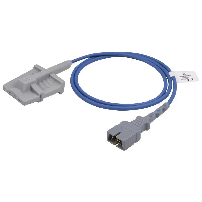
🔗 Reduce SpO₂ False Alarms with Quality Sensors
Worn-out or low-quality SpO₂ sensors are one of the most common — and most preventable — sources of false low-oxygen alarms. MedLinket manufactures compatible SpO₂ sensors for Philips, GE, Mindray, Masimo, and Nellcor monitors with ±2% accuracy across 70–100% SpO₂ range.
Bridge copy: If repeated false desaturation alarms continue after repositioning the probe and checking the cable, the next likely cause is an aging, poorly fitting, or technology-mismatched sensor. Here are a few commonly selected replacement options for adult monitoring setups:
Reading about SpO₂ alarms? Continue here for the complete parameter guide:
→ SpO₂ Low Alarm: Complete Troubleshooting Guide
Heart Rate Alarms: Tachycardia and Bradycardia
Heart rate (HR) alarms trigger when the monitored heart rate falls outside the set limits. The ECG-derived heart rate is generally more reliable for arrhythmia detection, while the pulse rate from SpO₂ confirms a mechanically effective heartbeat. When HR and PR values diverge significantly, that itself is a clinical finding worth investigating.
| Heart Rate Alarm | Typical Threshold | Common Causes | First Response |
|---|---|---|---|
| HR High (Tachycardia) | >120–150 BPM | Pain, fever, anxiety, dehydration, medication, SVT, VTach | Assess patient, check rhythm on ECG, review recent events |
| HR Low (Bradycardia) | <50–60 BPM | Athletic conditioning, sleep, beta-blockers, heart block, vagal response | Assess patient, check ECG rhythm, review medications |
| Asystole / VFib | No QRS detected / chaotic rhythm | True cardiac arrest OR lead disconnection | Immediately look at the patient — if unresponsive, initiate code |
⚠️ The Asystole Alarm Trap: One of the most common sources of "code blue" false activations is an asystole or VFib alarm caused by a disconnected ECG lead wire — not actual cardiac arrest. Before activating an emergency response, take 3 seconds to physically look at the patient. If alert and talking, the alarm is almost certainly a lead disconnection.
When Heart Rate Alarms Require Escalation
-
Escalate immediately: Sustained HR >150 BPM with symptoms, any new wide-complex tachycardia, HR <40 BPM with hypotension
-
Monitor and assess: Sinus tachycardia 100–130 BPM with pain/fever/post-op context. Sinus bradycardia 45–60 BPM in a comfortable patient on beta-blockers or during sleep
-
Likely false alarm: Sudden brief spikes that immediately self-correct, coinciding with patient movement
Blood Pressure Alarms: High, Low, and Failed Readings
NIBP (non-invasive blood pressure) monitoring uses the oscillometric method: the cuff inflates to occlude arterial flow, then slowly deflates while the monitor detects pressure oscillations. The strongest oscillation point corresponds to the MAP (Mean Arterial Pressure), and systolic and diastolic values are derived algorithmically.
| BP Alarm | Typical Threshold | When to Escalate |
|---|---|---|
| BP High (Hypertensive Urgency) | SBP >180 or DBP >120 mmHg | Immediately — especially with symptoms (headache, vision changes, chest pain) |
| BP Low (Hypotension) | SBP <90 or MAP <65 mmHg | Immediately if signs of poor perfusion (altered mental status, cold extremities) |
| NIBP Measurement Failed | No reading obtained | Troubleshoot: check cuff size, placement, patient movement, hose connections |
"Measurement Failed" — The Most Common NIBP Alarm
| Cause | How to Identify | Solution |
|---|---|---|
| Wrong cuff size | Cuff index line outside range marking | Measure arm circumference, select correct size |
| Patient movement | Patient moved during measurement | Retry when patient is still |
| Arrhythmia | Irregular rhythm on ECG | Use manual BP; consider IBP monitoring for critical patients |
| Cuff over clothing | Fabric between cuff and skin | Place cuff on bare arm; max 2mm fabric thickness |
| Kinked or leaking hose | Cuff doesn't fully inflate | Check hose for kinks, inspect connectors, replace if needed. For connector specs by brand, see our NIBP hose connector specifications reference |
If NIBP measurement failures persist after checking the cuff and hose, the issue may be deeper — our NIBP measurement errors troubleshooting guide walks through systematic diagnosis of oscillometric algorithm failures, air leak detection, and module-level issues. When the cuff inflates partially or not at all, we also keep a dedicated walkthrough for a cuff that won't inflate that isolates pump, valve, hose, and leak faults in order.
📚 Deep Dive: Blood Pressure Alarm on Monitor: Troubleshooting Guide — Complete guide to diagnosing BP alarm causes and solutions.
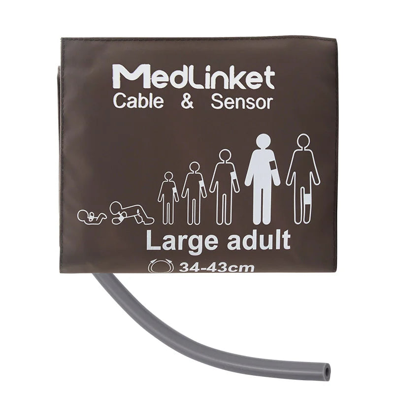
🔗 NIBP Cuffs and Hoses That Fit Right
Wrong cuff size is the single most common source of inaccurate blood pressure readings. MedLinket offers the full range of NIBP cuffs from neonatal (3–6 cm) through adult extra-large (32–42 cm) and thigh (42–54 cm), all latex-free and DEHP-free.
Tip: If repeated “measurement failed” alarms are tied to cuff sizing, poor wrap fit, or cuff wear, a correctly sized replacement cuff is often the fastest fix — for larger arms, a reusable option like our Reusable NIBP Cuff — Adult Large ($12.00, 40% off, fits 34–43 cm) is also included in the 3-accessory bundle near the end of this guide.
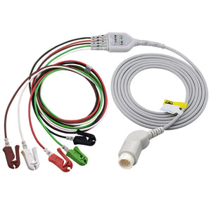
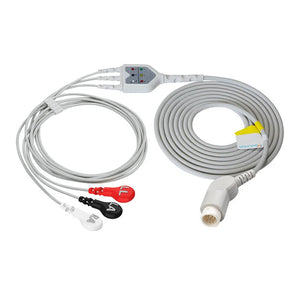
ECG Alarms: Leads Off, Arrhythmia, and Artifact
ECG monitoring generates some of the highest-volume and most safety-critical alarms in any hospital unit. The ECG signal pathway includes the patient's heart, ECG electrodes (skin contact), ECG lead wires (signal conductors), ECG trunk cables (connection to monitor), and the monitor's processing algorithm. A problem at any point triggers an alarm — and the vast majority originate from the electrode-to-skin interface, not from the patient's heart.
| ECG Alarm | Meaning | First Response |
|---|---|---|
| Leads Off | One or more ECG electrodes have lost electrical contact with the skin | Check each electrode and lead wire connection; replace dried-out electrodes |
| VFib / VTach | Monitor detects ventricular fibrillation or tachycardia | Look at the patient immediately. If unresponsive, initiate code. If awake, likely artifact |
| Asystole | No electrical activity detected (flatline) | Assess patient first. True asystole = code. Lead disconnect = fix the lead |
| Arrhythmia | Irregular rhythm pattern (PVCs, AFib, etc.) | Assess patient, verify rhythm, document, notify physician if new |
| ST Change | ST segment elevation or depression beyond set limit | Could indicate ischemia — obtain 12-lead ECG, notify physician |
| Artifact / Noisy Signal | Excessive baseline wander, 50/60 Hz interference, or motion artifact | Check skin prep, electrode adhesion, cable routing, interference sources |
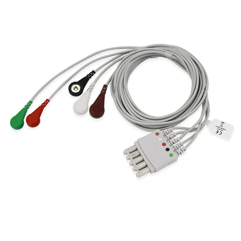
The "Leads Off" Alarm: The #1 Most Common ECG Alarm
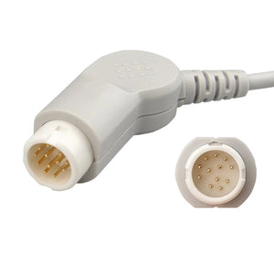
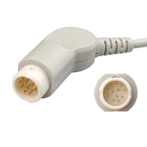
Ask any bedside nurse what alarm they hear most often, and the answer is almost universally "leads off." Common culprits include dried-out electrode gel (electrodes older than 24 hours), diaphoresis, chest hair preventing gel-to-skin contact, and worn snap connectors on ECG lead wires. If you're replacing lead wires and need to verify the correct connector type for your monitor, our ECG cable connector types technical guide covers the differences between snap, clip, grabber, and banana-style terminations across brands.
📚 Deep Dive: ECG Leads Off Alarm: How to Fix — Step-by-step guide to systematically diagnose and resolve leads-off alarms, including which specific lead to check first.
Bridge copy: For recurring “leads off” and artifact alarms, replacing aging lead wires is often the fastest corrective action after skin prep and electrode checks. These are practical replacements for common bedside monitor platforms:
ECG Interference: Three Types, Three Solutions
| Artifact Type | Appearance | Common Cause | Solution |
|---|---|---|---|
| 50/60 Hz Interference | Regular, fine "fuzzy" baseline | Nearby electrical equipment, poor grounding, damaged cable shielding | Check RL electrode, unplug nearby devices, replace damaged cables. Persistent interference often traces back to degraded cable shielding — biomedical staff can test cable impedance to confirm |
| Muscle (EMG) Artifact | Irregular, spiky, chaotic baseline | Patient shivering, movement; electrodes on muscle bulk | Reposition electrodes to flatter bony areas, warm patient |
| Baseline Drift | Slow rolling undulation | Respiratory movement, poor electrode adhesion, dried gel | Replace electrodes, improve skin prep |
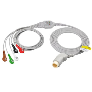
🔗 ECG Cables and Electrodes That Reduce False Alarms
Offset (eccentric) ECG electrodes are specifically designed to reduce artifact caused by cable tension and patient movement. In MedLinket's internal testing, traditional center-snap electrodes showed baseline drift up to 7,000 μV during standardized click experiments — while offset electrodes were virtually unaffected. The patented neck-relief structure absorbs cable tension so it never reaches the sensing gel-skin interface.
Technical and Equipment Alarms
Technical alarms signal issues with the monitoring hardware itself. While lower priority than physiological alarms, ignoring them can lead to loss of monitoring.
| Technical Alarm | What It Means | Response |
|---|---|---|
| Sensor Off / Disconnected | The SpO₂ sensor, temperature probe, or other accessory is not detected | Reconnect sensor or cable; check connector pins — and confirm you're matching the correct Philips SpO₂ connector generation (7-, 8-, or 9-pin) when swapping sensors |
| Low Battery | Monitor battery below critical threshold | Connect to wall power immediately |
| Check Sensor / Replace Sensor | Sensor malfunctioning or end-of-life | Replace with a known-good unit. If you're validating a compatible replacement, see our bench-tested Nellcor-on-Philips IntelliVue results across 30 combinations |
| Equipment Malfunction | Internal hardware or software fault | Note error code; contact Biomed. See our patient monitor error codes troubleshooting guide to decode common manufacturer-specific error messages before calling |
| NIBP Timeout | Scheduled BP measurement was not completed | Retry when patient is still |
When the monitor shows dashes (---) or zeros instead of readings, follow the systematic approach in our Patient Monitor No Reading Troubleshooting Checklist. For blank, flickering, or frozen displays, see Monitor Display Problems. And if the monitor won't power on at all, check Patient Monitor Not Turning On.
Universal Alarm Response Flowchart
Regardless of alarm type, follow this systematic approach:
🔔 ALARM SOUNDS
↓
STEP 1: LOOK AT THE PATIENT (not the monitor)
→ Is the patient in visible distress? Is the patient responsive?
↓
YES (distress) → Initiate emergency response. Call for help, begin intervention.
NO (patient appears OK) → Proceed to Step 2
↓
STEP 2: CHECK THE WAVEFORM / READING
→ Is the waveform clean? Does the reading match the clinical picture?
↓
Reading matches → CLINICAL INTERVENTION (true alarm — treat the cause)
Reading doesn't match → Proceed to Step 3
↓
STEP 3: CHECK EQUIPMENT
→ Sensor/electrode attached? Cable connected? Accessory compatible?
↓
Fix the issue → Reassess
Still not resolved → Replace accessory
Still not resolved → Contact Biomed
📋 The Golden Rule: Always assess the patient first, then the equipment. This prevents both treating a non-existent emergency (loose sensor) and ignoring a real one (assumed false alarm).
Prefer a quick visual walkthrough? Watch this short alarm-response video below:
Alarm Fatigue: The Hidden Safety Crisis
Alarm fatigue is the desensitization that occurs when clinicians are exposed to an overwhelming number of alarms — the vast majority clinically insignificant. It is consistently ranked among the top technology safety hazards in healthcare. The Joint Commission has made alarm management a National Patient Safety Goal since 2014.
| Statistic | Data |
|---|---|
| Percentage of non-actionable alarms | 85–99% |
| Alarms per ICU patient per day | 150–400+ |
| Increase in error probability per alarm interruption | 25% |
| Alarm-related deaths reported to FDA (5-year period) | 500+ |
Alarm fatigue is not a failure of individual nurses — it's a systems problem. Contributing factors include excessive non-actionable alarms, default alarm settings not tailored to patients, poor-quality ECG electrodes and SpO₂ sensors, inadequate skin preparation, and high nurse-to-patient ratios.
📚 Deep Dive: False Alarms on Patient Monitors: Causes and Prevention — Detailed strategies for every parameter, with evidence-based prevention protocols.
7 Proven Strategies to Reduce False Alarms
1. Proper Skin Preparation and Electrode Management
This single intervention can reduce ECG-related false alarms by up to 50%. Clean skin with alcohol, allow to dry, lightly abrade until slightly pink, clip excessive hair. Replace all ECG electrodes every 24 hours. For detailed electrode placement technique, see our 12-Lead ECG Placement Guide.
2. Patient-Specific Alarm Customization
Default thresholds are not optimized for any individual patient. A COPD patient with baseline SpO₂ of 88% will alarm constantly on standard settings. A well-conditioned athlete with resting HR of 48 BPM shouldn't trigger bradycardia alarms. Customize at the start of every shift. Alarm customization changes should be documented per your facility's protocol — see our guide on documentation and compliance record-keeping for best practices.
3. Use Quality, Compatible Monitoring Accessories
Old SpO₂ sensors with worn LEDs produce noisy signals. Damaged ECG cables pick up interference. Ill-fitting NIBP cuffs cause repeated measurement failures. Investing in quality, properly compatible accessories pays for itself. Not sure whether to choose original or compatible? See our guide on OEM vs Compatible Accessories for the clinical perspective, or our detailed OEM vs. compatible parts comparison from a BMET perspective for the engineering and cost analysis.
Bridge copy: If you want a simple starting point, think in terms of the three accessory types most often tied to false alarms: one reliable SpO₂ sensor, one dependable ECG cable set, and one correctly sized NIBP cuff. The product options below align with the most common alarm-related replacement scenarios covered in this article:
One reliable SpO₂ sensor, one dependable ECG leadwire, and one correctly sized NIBP cuff — enough to re-equip one bedside monitor
4. Implement Alarm Delay Settings
Many modern monitors allow brief delays (10–15 seconds) to filter transient, self-correcting events. Work with your biomedical engineering team to identify appropriate alarm types for short delays. Proper calibration of patient monitor accessories should be verified before adjusting alarm delays, as a miscalibrated sensor combined with delayed alarming could mask a genuine event.
5. Regular Cable and Sensor Inspection
| Accessory Type | Recommended Replacement | Signs It Needs Replacing Sooner |
|---|---|---|
| Reusable SpO₂ sensors | Every 12–18 months | Inconsistent readings, physical damage |
| ECG trunk cables | Every 2–3 years | Intermittent signal loss, connector corrosion |
| ECG lead wires | Every 6–12 months | Loose snap connectors, intermittent "leads off" |
| Disposable ECG electrodes | Every 24 hours | Edges curling, gel dried, signal artifact |
| Reusable NIBP cuffs | 1–2 years | Bladder leaks, velcro worn |
Biomedical engineering teams should incorporate these replacement intervals into their patient monitor preventive maintenance checklist. For detailed testing procedures on cables and sensors, see our medical cable inspection and testing methods guide.
📚 Full details: Accessory Replacement Schedule: When to Change
6. Staff Education and Alarm Response Protocols
Education programs should cover: proper ECG electrode placement, SpO₂ sensor positioning, the difference between "silence" and "disable," and patient-specific alarm customization workflows.
7. Multidisciplinary Alarm Management Teams
The most successful programs involve collaboration between nursing, biomedical engineering, physicians, and administration. One children's hospital reduced alarms from 180 per patient per day to 40 through exactly this team-based approach. If you're unsure which issues need engineering support, our guide on When to Call Biomed vs Troubleshoot Yourself provides a clear decision framework.
Why Hospitals in 120+ Countries Trust MedLinket Monitoring Accessories
Since 2004, MedLinket (Shenzhen Med-Link Electronics Tech Co., Ltd., NEEQ stock code: 833505) has specialized in manufacturing high-quality patient monitor accessories designed to reduce false alarms and improve signal quality.
-
🏭 21 Years of Manufacturing: 3 factories (Shenzhen, Shaoguan, Indonesia), 3,500+ molds, 16,651+ product variants
-
✅ Full Regulatory Compliance: FDA 510(k) (19 clearances), CE MDR, ISO 13485:2016, MDSAP, NMPA
-
🌍 Global Hospital Network: 120+ countries, 2,000+ hospitals, including UK Royal Victoria Hospital
-
🔧 30+ Compatible Brands: Philips, GE, Mindray, Dräger, Masimo, Nellcor, and more — see the complete multi-brand compatibility matrix
-
🛡️ $5M Product Liability Insurance — individual certificates available for distributors
-
🔬 Patented Technology: 45 utility model + 8 invention patents including offset electrode and over-temperature protection
Need help identifying the right accessories for your monitors? Use our cable identification guide or contact us directly. For Philips and GE systems, our Philips & GE monitor service guide provides model-specific accessory references. For Mindray-based facilities, see our Mindray monitor technical resources. Procurement teams vetting new suppliers can use our vendor qualification checklist for medical accessories and our guide on how to evaluate third-party medical accessories to streamline the approval process. Quality accessories also deliver long-term cost savings for BMET departments by reducing false alarm rates, repeat purchases, and unplanned downtime.
📩 Contact: shopify@medlinket.com | WhatsApp: +852 6467 3105
MOQ: Flexible | Lead Time: 7–15 business days | Samples Available
Frequently Asked Questions
Why does the hospital monitor keep beeping even though the patient looks fine?
This is almost always a technical or equipment issue. The most common causes are: a loose or dried-out ECG electrode triggering "leads off," an SpO₂ sensor that has shifted on the finger, or alarm thresholds not customized for the patient's baseline. Check all connections, replace electrodes if older than 24 hours, and verify alarm limits match the patient's condition. If the issue persists, try a fresh sensor or cable to rule out equipment degradation.
Can I silence alarms on a patient monitor? What's the difference between "silence" and "disable"?
Silence (or "pause") temporarily mutes the audible alarm for 60–120 seconds while keeping visual indicators active. The alarm re-sounds if the condition persists. Disable turns off a specific alarm entirely. Silencing is appropriate during known transient events (repositioning, suctioning). Disabling should only be done with a physician order and careful documentation.
What should I do first when any alarm sounds?
Always assess the patient first, then assess the equipment. Physically look at the patient: responsive? In distress? Visible cyanosis or apnea? This 3-second visual assessment tells you more than the monitor. If the patient looks well, check equipment. If in distress, call for help and begin intervention.
What percentage of hospital alarms are false?
Published research consistently reports that 85–99% of hospital monitor alarms are either false or clinically insignificant. This proportion drives alarm fatigue. Reducing it through better accessories, proper skin prep, and patient-specific alarm limits is one of the most impactful safety improvements any unit can make.
How do I know if a VFib alarm is real or just a loose lead?
Look at the patient immediately. If alert and talking, the alarm is lead artifact — not true VFib. True VFib presents with an unresponsive patient without a palpable pulse. The monitor often still shows a pulse rate from the SpO₂ sensor even when the ECG waveform looks chaotic — if SpO₂ PR is normal and stable, the ECG alarm is almost certainly artifact.
Related Articles in This Series
This article is part of the Hospital Monitor Reading & Accessories Guide. Explore the dedicated alarm guides for each parameter:
-
Patient Monitor Accessories: Complete Guide by Parameter Type
-
BMET Resource Hub: Technical Guides for Biomedical Engineers
Medical Disclaimer: This article is intended for educational purposes for healthcare professionals and clinical staff. It does not constitute medical advice. Always follow your facility's protocols and consult qualified medical professionals for patient care decisions.
Clinical Education Team
Our clinical education team includes cardiologists and emergency medicine specialists with extensive experience in acute MI management. This guide reflects current AHA/ACC guidelines combined with practical clinical techniques.