📚 BMET Resource Hub › Maintenance › Cable Inspection
✍️ By MedLinket Clinical Engineering Team · Est. 2004 · ISO 13485 & FDA 510(k) certified manufacturer
🔍 Reviewed by BMETs with 15+ years of multi-brand cable service experience
📅 Last Updated: March 2026 · 📖 Reading time: ~10 min
⚡ Quick Answer
Cable inspection for patient monitor accessories covers three phases: visual inspection for jacket damage and connector wear, continuity and insulation resistance testing per IEC 62353, and leakage current measurement to verify patient safety compliance. This guide provides step-by-step procedures, pass/fail criteria, and documentation requirements for each phase.
📌 Article Scope: This page covers cable inspection procedures — how to test patient monitor cables step by step.
For cable material and shielding requirements (what specifications to look for), see medical cable specifications. Cable inspection is one component of the overall preventive maintenance checklist.
📑 Table of Contents

When to Inspect Cables
Cable inspection should occur in four situations. Include these triggers in your department's PM checklist and documentation procedures:
Tools and Equipment Required
📥 Download: Cable Inspection Worksheet (PDF)
Print this 3-phase inspection worksheet before you start. Covers visual inspection (jacket + connector checklists), electrical testing (continuity, insulation resistance, shield integrity with IEC 62353 pass/fail values), safety testing (leakage current limits), and a final pass/fail decision matrix. Record your results directly on the sheet.

Visual Inspection
Visual inspection catches the majority of cable problems. Based on MedLinket's warranty return data across 2,000+ hospital installations (2022–2025), approximately 60% of failed cables show visible damage that could have been caught during routine visual inspection before the cable caused clinical problems.
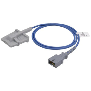
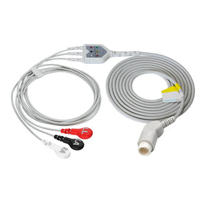
🔍 Cable Jacket Inspection
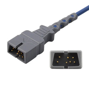
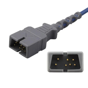
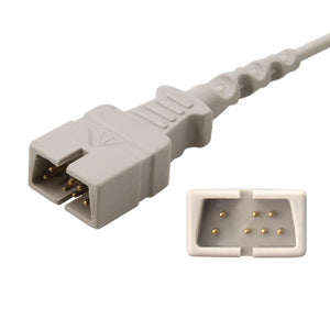
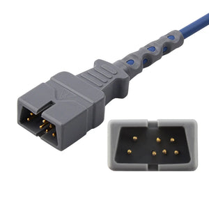
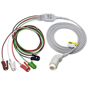
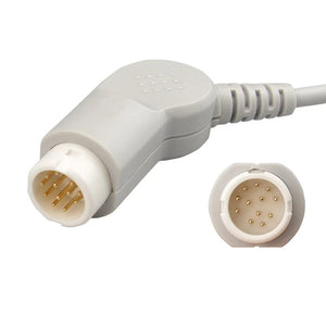
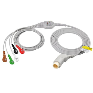
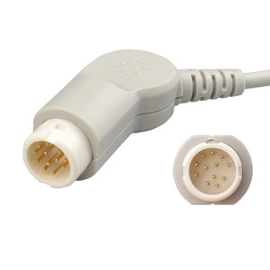
🔌 Connector Inspection

Electrical Testing
Electrical testing verifies the cable's internal integrity. All values below are per IEC 62353 (recurrent test and test after repair of medical electrical equipment) and IEC 60601-1 (medical electrical equipment — general requirements for basic safety). For the material requirements these tests verify, see the medical cable specifications guide.
📏 Continuity Testing
Purpose: Verify each conductor has a continuous electrical path from one connector end to the other, with no open circuits or high-resistance joints.
💡 BMET Field Tip
The flex test (Step 3) is the most important part of continuity testing. A cable can pass static continuity while having an intermittent conductor break that only opens under bending. This is the most common cause of "works sometimes, doesn't work other times" complaints from nursing staff. As experienced BMETs note: "If you're not flexing during continuity testing, you're not really testing."
⚡ Insulation Resistance Testing
Purpose: Verify the insulation between conductors and between conductors and the cable shield has not degraded, which would increase patient leakage current risk.
⚠️ Safety Warning
Insulation testing applies 500 VDC to the cable. Never test a cable while connected to a patient, a monitor, or a sensor. Ensure the cable is completely isolated before applying test voltage. Follow your facility's lockout/tagout procedures for electrical testing of medical equipment.
🛡️ Shield Continuity Testing
Purpose: Verify the cable shield provides an unbroken path from the shield at one end to the ground/shield pin at the connector. A broken shield cannot reject EMI — the cable may pass continuity testing while still producing noisy signals.
Electrical Safety Testing
Electrical safety testing verifies that the cable assembly (cable + connected accessories) meets patient leakage current limits defined in IEC 60601-1. This requires a calibrated electrical safety analyzer — a standard multimeter cannot perform these measurements.
Type CF cables (ECG cables, intracardiac leads) have the strictest limits because they provide a direct electrical path to the heart. Any cable that exceeds these limits must be immediately removed from service. For calibration verification schedules for your safety analyzer, see calibration requirements for patient monitor accessories.

Parameter-Specific Inspection Notes
In addition to the general procedures above, each cable type has specific inspection considerations:
Pass/Fail Decision Matrix
⚠️ Important
Medical cables should never be spliced, soldered, or otherwise repaired. A repaired cable cannot be guaranteed to meet IEC 60601-1 safety requirements for insulation, creepage distance, or leakage current. Always replace with a new cable — whether OEM or compatible.
From the r/BMET Community
Shared by u/lx_SpAwN_xl in r/BMET
Field BMETs on Reddit regularly share real-world experience on cable failure modes, inspection techniques, and when to pull cables from service. Community discussions like this one offer practical insight that complements formal IEC procedures.
💬 Read the Discussion on Reddit →Documentation and Record-Keeping
Proper documentation of cable inspection results is required for Joint Commission, CMS, and other accreditation compliance. Record the following for each cable inspected:

For complete documentation templates and compliance requirements, see BMET documentation and compliance record-keeping.
🔧 Need Replacement Cables?
When inspection reveals a cable that needs replacement, MedLinket manufactures compatible cables for all major monitor brands — ISO 13485 certified, FDA 510(k) registered, 100% factory tested. Every cable passes the same inspection tests described in this guide before shipping. For evaluating compatible vs OEM options, see our OEM vs compatible parts analysis.
Frequently Asked Questions
❓ How often should patient monitor cables be inspected?
Cables should be visually inspected at every preventive maintenance cycle (typically every 6–12 months), with full electrical testing annually or per manufacturer recommendation. High-use cables in ICU/OR environments may warrant more frequent inspection. Cables should also be inspected whenever a monitoring parameter shows unexplained artifact, noise, or intermittent readings.
❓ What is the minimum insulation resistance for a medical cable per IEC 62353?
The minimum acceptable insulation resistance is 2 MΩ when tested at 500 VDC between each conductor and the cable shield or ground. New cables typically measure well above 100 MΩ. Any cable measuring below 2 MΩ should be removed from service immediately, as degraded insulation increases patient leakage current risk. For material specifications that affect insulation performance, see medical cable specifications.
❓ Can I use a standard multimeter for medical cable testing?
A standard DMM is adequate for continuity testing and basic pin verification. However, insulation resistance testing requires a dedicated insulation tester (megohmmeter) capable of applying 500 VDC per IEC 62353. Leakage current testing requires a calibrated electrical safety analyzer. For safety analyzer calibration schedules, see calibration requirements.
❓ What are the most common cable failure points?
Based on MedLinket's warranty return analysis across 2,000+ hospital installations (2022–2025), approximately 75% of cable failures occur within 5 cm of the connector — the cable-connector junction where bending stress concentrates. The second most common failure point is the first 15 cm of cable near the connector. Connector pin corrosion from cleaning solutions is the third most common cause.
❓ Should I test cables with or without sensors attached?
Test both ways. First, test the cable alone to isolate cable-only faults. Then test the complete assembly (cable + sensor/transducer) to verify the full signal path. If the cable alone passes but the assembly fails, the fault is in the sensor or the cable-to-sensor connection.
❓ What visual signs indicate a cable needs replacement rather than repair?
Replace when you find: exposed conductors or shield visible through jacket damage, connector housing cracks exposing internal components, discoloration or permanent stiffening of the jacket, permanent kinks that don't straighten, or any cable that fails insulation resistance testing below 2 MΩ. Medical cables should never be spliced or repaired — a repaired cable cannot be guaranteed to meet IEC 60601-1 safety requirements. For vendor selection when ordering replacements, see the vendor qualification checklist.
Related BMET Resources
📐 Cable Specs & Pinouts
🔧 Maintenance & Compliance
🛠️ Troubleshooting
About MedLinket
MedLinket (est. 2004) manufactures compatible patient monitor cables and accessories for all major brands. Every cable undergoes 100% factory electrical testing — continuity, insulation resistance, and functional verification — before shipping. Three self-owned factories (Shenzhen, Shaoguan, Indonesia), 3,500+ molds, 16,651+ product variants. ISO 13485 certified, FDA 510(k) registered (19 clearances), CE marked, MDSAP audited. Serving 2,000+ hospitals across 120+ countries with $5M product liability coverage.