Quick Answer: This reference covers SpO2 connector pinout configurations for the major pulse oximetry technologies — Nellcor OxiMax (9-pin D-sub), Masimo SET (14/15-pin proprietary), Philips FAST (8-pin D-sub), GE TruSignal (11-pin Ohmeda), and Mindray (proprietary 7-pin) — with signal descriptions for each pin. All SpO2 sensors use the same five core signals (red LED drive, IR LED drive, photodiode return, ground, sensor ID) but implement them through incompatible connector and protocol designs.

This page covers the electrical pinout and signal specifications of SpO2 connectors. To check which SpO2 sensor is compatible with your specific monitor model, see our patient monitor accessory compatibility matrix. For troubleshooting SpO2 errors after sensor replacement, see our patient monitor error codes troubleshooting guide. For cable shielding and impedance requirements that affect signal quality, refer to our medical cable specifications guide.
1. How SpO2 Sensors Work: Signal Architecture
Every SpO2 sensor operates on the same physical principle: two LEDs (red at ~660 nm and infrared at ~905–940 nm) transmit light through perfused tissue, and a photodiode on the opposite side detects the transmitted light. The ratio of red to infrared absorption, modulated by arterial pulsation, determines oxygen saturation.
From an electrical engineering perspective, the sensor cable carries drive signals to the LEDs, returns the photodiode's analog signal to the monitor's SpO2 module, and transmits sensor identification data that tells the module which LED wavelengths and calibration coefficients to use. The differences between SpO2 technologies lie not in the fundamental measurement principle, but in how these signals are encoded, multiplexed, and identified across the connector interface.
2. The Five Core Signals in Every SpO2 Connector
Despite the diversity of connector designs, every SpO2 sensor interface carries the same five functional signal groups. Understanding these signals is the foundation for interpreting any manufacturer's pinout.
| Signal | Function | Typical Characteristics | Failure Mode if Broken |
|---|---|---|---|
| Red LED Drive | Powers the red LED (~660 nm wavelength) in the sensor | Pulsed current, typically 20–50 mA peak; time-multiplexed with IR LED | "Sensor off" or no waveform; monitor may display "Low signal quality" |
| IR LED Drive | Powers the infrared LED (~905–940 nm) in the sensor | Pulsed current, time-multiplexed with red LED; alternating drive cycle | "Sensor off" or erratic SpO2 values; waveform may be absent or noisy |
| Photodiode Return | Carries the detected light signal from photodiode back to the monitor | Low-level analog current (nanoamps to microamps); highly sensitive to noise | No reading; "Sensor off"; or wildly fluctuating SpO2 if intermittent |
| Ground / Shield | Signal reference and electromagnetic shielding | Connected to cable shield; critical for noise rejection | Excessive artifact; noisy waveform; motion artifact amplification |
| Sensor ID / Calibration | Identifies sensor type to the module; provides LED wavelength calibration data | Coded resistor (Nellcor), digital signal (Masimo), or resistor + digital (Philips) | "Incompatible sensor" error; "Unsupported sensor"; module refuses to read |
Signal characteristics based on published SpO2 module service manuals and IEC 60601-1-2:2014 EMC requirements for medical devices.
3. NELLCOR OxiMax — 9-Pin D-Sub Pinout
Nellcor OxiMax is one of the most widely deployed SpO2 technologies in hospitals worldwide. The system uses a standard 9-pin D-sub (DB9) connector with a specific pin assignment. OxiMax sensors contain a coded resistor on the sensor ID pins that communicates the LED wavelength pair and calibration coefficients to the module.
| Pin | Signal | Description | Wire Color (typical) |
|---|---|---|---|
| 1 | Shield / Drain | Cable shield drain wire | Bare / Foil |
| 2 | Red LED Anode (+) | Drive current to red LED (~660 nm) | Red |
| 3 | IR LED Anode (+) | Drive current to IR LED (~905 nm) | — |
| 4 | LED Cathode (−) | Common return for both LEDs | Black |
| 5 | Photodiode Anode (+) | Detected signal from photodiode | Blue / White |
| 6 | Photodiode Cathode (−) | Photodiode signal return | Green |
| 7 | Sensor ID (Rcal) | Coded resistor — wavelength calibration | — |
| 8 | Sensor ID Return | Return path for calibration resistor | — |
| 9 | Ground | Signal ground reference | Black / Green |
Pin assignments based on Nellcor OxiMax service documentation. Actual wire colors may vary by sensor manufacturer and model.
Compatible Nellcor OxiMax Products
Direct-connect sensors: Adult clip, Adult soft, Multi-site Y-type. Short sensors: DS-100A, D-YS multi-site. Adapter cables: DEC-8, DOC-10. Disposable sensors: MAX-A adult, MAX-P pediatric, MAX-N neonate, MAX-I infant.
4. MASIMO SET — 14/15-Pin Proprietary Pinout
Masimo SET (Signal Extraction Technology) uses a proprietary connector with a higher pin count than Nellcor. The additional pins carry digital sensor identification and advanced calibration data. Masimo's LNCS (Low Noise Cable System) and M-LNCS sensor families use slightly different connector variants but share the same signal architecture.
| Pin Group | Signal | Description |
|---|---|---|
| Pins 1–2 | Red LED Drive | Drive current to red LED (~660 nm); differential pair |
| Pins 3–4 | IR LED Drive | Drive current to IR LED (~940 nm); differential pair |
| Pins 5–6 | Photodiode Signal | Detected optical signal; differential pair for noise rejection |
| Pins 7–8 | Ground / Shield | Signal reference and cable shielding |
| Pins 9–11 | Digital Sensor ID | Masimo proprietary digital identification — sensor type, calibration data, usage tracking |
| Pins 12–14/15 | Reserved / Additional | Additional calibration, future expansion, or cable-type identification |
Signal groups based on Masimo SET technical documentation. Exact pin-level assignments are proprietary; the table shows functional signal groups.
Compatible Masimo Products
Adapter cable: M-LNC-10 (2525), 0012-00-1653. Short sensor: 1864, LNOP DCI (1269), 3178. Disposable: 4000 adult, 4001 pediatric, 4002 infant, 4003 neonate, LNCS Neo.
5. PHILIPS FAST — 8-Pin D-Sub Pinout
Philips FAST (Fourier Artifact Suppression Technology) uses an 8-pin D-sub connector for direct-connect sensors on IntelliVue monitors. Philips also supports Nellcor OxiMax and Masimo SET through interchangeable SpO2 modules with different adapter cables.
| Pin | Signal | Description |
|---|---|---|
| 1 | Red LED Drive | Drive current to red LED (~660 nm) |
| 2 | IR LED Drive | Drive current to IR LED (~940 nm) |
| 3 | LED Common (−) | Common cathode return for both LEDs |
| 4 | Photodiode (+) | Detected optical signal |
| 5 | Photodiode (−) | Photodiode return / reference |
| 6 | Sensor ID | Calibration resistor — identifies sensor type and wavelength pair |
| 7 | Shield / Ground | Cable shield and signal ground |
| 8 | Sensor ID Return | Return path for sensor identification circuit |
Pin assignments based on Philips IntelliVue service manual documentation. Philips adapter cables (M1940A, M1941A, M1943A) route these signals to Nellcor or Masimo sensor formats when non-FAST modules are installed.
Compatible Philips FAST Products
Direct-connect: M1191BL adult clip, M1192A pediatric, M1194A ear clip, M1196A neonatal. Short sensors: M1191A, M1195A, M1192T. Adapter cables: M1940A, M1941A, M1943A/NL, 989803148221, M1020-61100, M1900B.
For complete Philips monitor accessory compatibility including ECG, NIBP, IBP, and temperature, see our Philips & GE patient monitor service guide.
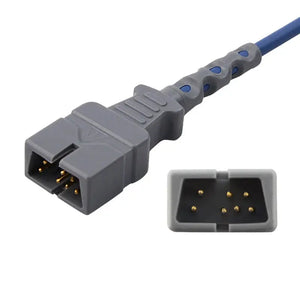
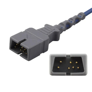
6. GE TruSignal — 11-Pin Ohmeda Pinout
GE TruSignal is GE Healthcare's proprietary SpO2 technology. It uses an 11-pin Ohmeda-style round connector. GE CARESCAPE monitors may also support Masimo SET and Nellcor OxiMax through interchangeable SpO2 modules — verify which module is installed before ordering sensors.
| Pin Group | Signal | Description |
|---|---|---|
| Pins 1–2 | Red LED Drive | Drive current to red LED |
| Pins 3–4 | IR LED Drive | Drive current to IR LED |
| Pin 5 | LED Common | Common cathode return |
| Pins 6–7 | Photodiode Signal | Detected optical signal and return |
| Pins 8–9 | Sensor ID | GE proprietary sensor identification |
| Pin 10 | Shield / Ground | Cable shield and signal reference |
| Pin 11 | Reserved | Future expansion / cable ID |
Signal groups based on GE Datex-Ohmeda service documentation. GE TruSignal sensors include a Datex-Ohmeda heritage connector that is mechanically distinct from Nellcor and Masimo interfaces.
Compatible GE TruSignal Products
Direct-connect: TS-SA4-GE adult — a flat 11-pin dual-keyed GE connector built to the TruSignal pinout above ($100, 17% off), TS-E4-GE ear clip, OXY-F4-N. Adapter cables: 2021406-001, TS-G3, TS-N3. Disposable: TS-AP-25, TS-AF-25, TS-PAW-10.
MedLinket manufactures compatible SpO2 sensors and adapter cables for all major technologies — Nellcor, Masimo, Philips FAST, GE TruSignal, and Mindray — with ISO 13485 certification and complete pinout compatibility.
Direct-Connect Sensors Adapter Cables Disposable Sensors7. MINDRAY — 7-Pin Proprietary Pinout
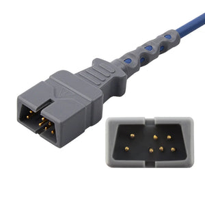
Mindray uses a proprietary 7-pin round connector for its native SpO2 technology on BeneVision, iPM, and iMEC series monitors. Mindray also supports Masimo and Nellcor modules on some models via separate SpO2 module slots.
| Pin | Signal | Description |
|---|---|---|
| 1 | Red LED Drive | Drive current to red LED |
| 2 | IR LED Drive | Drive current to IR LED |
| 3 | LED Common | Common cathode return |
| 4 | Photodiode (+) | Detected optical signal |
| 5 | Photodiode (−) | Photodiode signal return |
| 6 | Sensor ID | Coded resistor for sensor identification |
| 7 | Shield / Ground | Signal ground and cable shield |
Compatible Mindray Products
Direct-connect: 512FLH adult clip, Adult soft, Adult ear clip, Neonatal wrap. Adapter cables: 0010-20-42710, 115-020768-00, 115-023135-00. For complete Mindray accessory details, see our Mindray patient monitor technical resources.
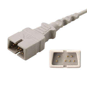
8. Nihon Kohden — 9-Pin Pinout
Nihon Kohden uses a 9-pin proprietary connector on BSM and Life Scope series monitors. The signal architecture follows the standard five-signal model with Nihon Kohden-specific sensor identification.
Compatible Nihon Kohden Products
Direct-connect: P205A/TL-220T/P225G. Short sensors: TL-201T. Adapter cables: JL-900P, JL-650P, JL-302T. Disposable: TL-271T adult, TL-272T pediatric, TL-273T neonate, TL-274T infant.
9. Adapter Cable Signal Routing
SpO2 adapter cables sit between the monitor's SpO2 module connector and the sensor connector. They serve two purposes: physical connector format conversion, and in some cases, passive signal conditioning (resistor networks or decoupling capacitors that are part of the technology-specific signal path).
| Monitor Brand | Module Type | Adapter Cable | Sensor Technology Supported |
|---|---|---|---|
| Philips IntelliVue | FAST module | M1941A | Philips FAST sensors |
| Philips IntelliVue | Nellcor OxiMax module | M1943A/NL | Nellcor OxiMax sensors |
| Philips IntelliVue | Masimo SET module | M1940A | Masimo SET sensors |
| GE CARESCAPE | TruSignal module | 2021406-001 | GE TruSignal sensors |
| GE CARESCAPE | Nellcor module | GE-specific Nellcor adapter | Nellcor OxiMax sensors |
| Mindray | Native module | 0010-20-42710 | Mindray native sensors |
| Mindray | Masimo module | 115-020768-00 | Masimo SET sensors |
| Nihon Kohden | Native module | JL-900P | Nihon Kohden sensors |
The Mindray adapter highlighted below is a textbook illustration of the rule above: the same connector shell is sold in OxiSmart, OxiMax, and M-tech variants at different part numbers, because the internal signal routing — not the plug — is what determines compatibility.
10. Continuity Testing and Fault Isolation
When an SpO2 sensor or cable is suspected of failure, BMETs can use a digital multimeter (DMM) to test continuity and isolate the fault to a specific signal path. Follow these safety precautions per IEC 62353 recurrent testing guidelines:
- Always disconnect the sensor/cable from the patient monitor before testing.
- Use the multimeter's built-in test current only — do not apply external voltage to the sensor.
- Test at both ends of the cable to isolate whether the fault is in the connector, the cable, or the sensor element.
LED Drive Lines (Red and IR)
Set the DMM to diode test mode. Place probes across the LED anode and cathode pins. The red LED should show a forward voltage of approximately 1.6–2.0 V. The IR LED should show approximately 1.1–1.4 V. An open circuit (OL) indicates a broken LED or severed wire. A short circuit (~0 V) indicates a shorted LED or pinched cable.
Photodiode Signal Path
Set DMM to diode test mode. The photodiode should show a diode drop (~0.4–0.7 V) in one direction and open circuit in the other. Readings at the connector end should match readings at the sensor end — a discrepancy indicates a cable break.
Sensor ID / Calibration Resistor
Set DMM to resistance mode (20kΩ range). Measure across the sensor ID pins at the connector. Nellcor OxiMax sensors typically show a calibration resistor between 750 Ω and 68 kΩ depending on sensor type. An open circuit on the ID pins is the most common cause of "incompatible sensor" errors. For systematic troubleshooting beyond cable testing, see our medical cable inspection and testing methods guide.
11. Cross-Technology Compatibility Summary
The following matrix summarizes which SpO2 technologies are electrically compatible with each other. The answer for all cross-technology combinations is the same: they are not compatible.
| Sensor ↓ / Module → | Nellcor OxiMax | Masimo SET | Philips FAST | GE TruSignal | Mindray |
|---|---|---|---|---|---|
| Nellcor OxiMax Sensor | ✓ Compatible | ✗ | ✗ | ✗ | ✗ |
| Masimo SET Sensor | ✗ | ✓ Compatible | ✗ | ✗ | ✗ |
| Philips FAST Sensor | ✗ | ✗ | ✓ Compatible | ✗ | ✗ |
| GE TruSignal Sensor | ✗ | ✗ | ✗ | ✓ Compatible | ✗ |
| Mindray Sensor | ✗ | ✗ | ✗ | ✗ | ✓ Compatible |
Each monitor may support multiple technologies through interchangeable modules — for example, a Philips IntelliVue can run FAST, Nellcor, or Masimo depending on which module is installed. The key is to match the sensor to the module, not the monitor brand. For complete which-fits-which lookup, see our patient monitor accessory compatibility matrix.
When purchasing compatible sensors from manufacturers like MedLinket, verify that the sensor is designed for the specific technology (not just the monitor brand). For a structured evaluation process when sourcing compatible SpO2 sensors, see our third-party accessory evaluation framework. For cost comparisons between OEM and compatible options, see our OEM vs compatible accessories analysis.
MedLinket produces SpO2 sensors and adapter cables compatible with Nellcor OxiMax, Masimo SET, Philips FAST, GE TruSignal, Mindray, and Nihon Kohden technologies — all ISO 13485 certified with verified pinout compatibility.
All SpO2 Sensors & Cables Short SpO2 SensorsFrequently Asked Questions
What is the difference between Nellcor OxiMax and Masimo SET connectors?
Nellcor OxiMax uses a 9-pin D-sub connector with a coded calibration resistor. Masimo SET uses a proprietary 14/15-pin connector with digital sensor identification. They are electrically incompatible — a Nellcor sensor cannot be used on a Masimo module, and vice versa. Each requires its own dedicated adapter cable and sensor family.
How many pins does a Philips FAST SpO2 connector have?
Philips FAST uses an 8-pin D-sub connector for direct-connect sensors. Some Philips modules support a 12-pin configuration for adapter cables interfacing with Nellcor or Masimo sensors. The 8-pin carries red LED drive, IR LED drive, photodiode signal, ground, and sensor identification signals. A compatible direct-connect example with this exact connector is the M1191BL adult soft sensor ($40, 33% off).
Can I use a multimeter to test SpO2 connector pin continuity?
Yes. You can verify continuity using diode-test or resistance mode. The red LED typically shows 1.6–2.0 V forward voltage; the IR LED shows 1.1–1.4 V. The photodiode shows a diode drop in one direction. Always disconnect from the patient monitor first, and only use the multimeter's built-in test current per IEC 62353 safety guidelines. For a complete testing procedure, see our cable inspection and testing methods.
Why does my SpO2 sensor show "incompatible sensor" after connecting?
This error means the sensor's technology protocol does not match the SpO2 module. Each technology uses a different digital handshake and sensor ID method. Verify that the sensor, adapter cable, and SpO2 module all belong to the same technology family. For systematic troubleshooting, see our patient monitor error codes guide.
What signals are carried on SpO2 sensor pins?
Every SpO2 sensor uses five core signals: red LED drive (~660 nm), infrared LED drive (~905–940 nm), photodiode return, ground/shield, and sensor identification (coded resistor or digital ID). Some technologies add calibration data and digital communication lines, which is why pin counts range from 7 to 15 across platforms.
Are SpO2 adapter cables technology-specific or universal?
Technology-specific. An adapter cable for Nellcor OxiMax will not work with Masimo SET sensors even if the physical connector fits. Adapter cables contain passive components that are part of the technology-specific signal path. Always match the adapter cable to the SpO2 module installed, not just the connector shape. A clear example is the Mindray 0010-20-42710 adapter ($40, 20% off), which is offered in separate OxiSmart, OxiMax, and M-tech versions of the same connector. For vendor evaluation when sourcing cables, see our vendor qualification checklist.
Related BMET Resources
- Return to BMET Resource Hub — Complete technical library for patient monitor accessories
- Patient monitor accessory compatibility matrix — Which sensor fits which monitor (cross-brand lookup)
- ECG cable connector types identification guide — Visual guide for ECG connectors
- NIBP hose connector specifications — Fitting types and dimensions by brand
- IBP cable pinout and signal specifications — IBP connector wiring reference
- YSI 400 vs 700 temperature probe comparison
- Medical cable specifications — Shielding, impedance, and material standards
- Medical cable inspection and testing methods — Visual, electrical, and safety testing
- Philips & GE patient monitor service guide
- Mindray patient monitor technical resources
- Patient monitor error codes troubleshooting
- Patient monitor PM checklist
- Calibration requirements
- BMET documentation and compliance
- How to evaluate third-party medical accessories
- OEM vs compatible patient monitor accessories
- Vendor qualification checklist
- BMET cost-saving strategies
Related Guides & Product Collections
- Understanding SpO2 sensors — Masimo, Nellcor, and neonatal options
- Compatible Masimo SpO2 sensors for multi-brand monitors
- How do SpO2 sensors work
- SpO2 sensor troubleshooting — why readings are inaccurate
- How to choose disposable SpO2 sensors
- How to identify which cables your monitor needs
- Direct-connect SpO2 sensors
- Short SpO2 sensors
- SpO2 adapter cables
- Disposable SpO2 sensors
- Masimo compatible
- Nellcor compatible
- Philips accessories
- GE Healthcare accessories
- Mindray accessories
- Nihon Kohden accessories