📚 Part of: BMET Resource Hub › Maintenance
✍️ By MedLinket Clinical Engineering Team
🔍 Reviewed by senior BMETs with 15+ years multi-brand PM experience
📅 Last Updated: March 2026 | 📖 Reading time: ~12 min
Quick Answer: A structured preventive maintenance checklist covering visual inspection, electrical safety testing (per IEC 62353), calibration verification, and documentation for every patient monitor accessory type — SpO2, ECG, NIBP, IBP, and temperature — aligned with Joint Commission requirements (EC.02.04.03). This guide provides the step-by-step PM workflow. For calibration-specific schedules and procedures, see our calibration requirements guide. For cable-specific inspection methods, see medical cable inspection & testing methods.
📌 Article Scope
This is a complete PM procedure guide — the step-by-step workflow for conducting preventive maintenance on patient monitors and their accessories. It covers what to inspect, how to test, and what to document.
Related but distinct guides:
• Calibration schedules & procedures → Calibration Requirements for Patient Monitor Accessories
• Cable inspection testing techniques → Medical Cable Inspection & Testing Methods
• Accessory replacement timing → Patient Monitor Accessory Replacement Schedule
• Compliance record-keeping requirements → BMET Documentation & Compliance Guide
📋 Table of Contents
- PM Schedule Recommendations
- Section 1: Pre-PM Documentation
- Section 2: Visual Inspection
- Section 3: Electrical Safety Testing
- Section 4: Functional Testing by Parameter
- Section 5: Alarm System Testing
- Section 6: Battery Testing
- Section 7: Accessory Inspection
- Section 8: Software / Firmware
- Section 9: Post-PM Documentation
- PM Tools Required
- Accessory Quality and PM Intervals
- Frequently Asked Questions
- Related BMET Resources
A comprehensive patient monitor preventive maintenance checklist is the backbone of any clinical engineering program. The Joint Commission standard EC.02.04.03 requires that medical equipment in accredited organizations receive documented maintenance activities — including inspection, testing, and maintenance — in accordance with the organization's maintenance strategies. But a checkbox on paper is not the same as a rigorous inspection.
This guide delivers a complete, step-by-step patient monitor PM checklist for BMETs — covering electrical safety, functional verification for every parameter, accessory inspection, battery optimization, alarm system testing, and documentation — built from manufacturer service guidelines, IEC 62353 (recurrent testing of medical electrical equipment), and over 20 years of field experience supporting patient monitor accessories globally.
According to data collected from MedLinket's technical support system (N=12,400+ support tickets, 2022–2025), approximately 65–70% of patient monitor service calls are related to accessory faults rather than monitor hardware failures. This means a thorough accessory-focused PM program can substantially reduce unplanned downtime.

PM Schedule Recommendations
PM frequency should be risk-stratified, not uniform across all devices. Patient monitors used in critical care environments have higher risk profiles and utilization rates than those in outpatient clinics. The AAMI EQ56 standard (Recommended Practice for a Medical Equipment Management Program) supports risk-based scheduling as an alternative to fixed annual intervals.
| Environment | Recommended PM Frequency | Rationale |
|---|---|---|
| ICU / CCU / OR | Every 6 months | Continuous use, critical patients, high accessory turnover |
| Step-down / Telemetry units | Every 6–12 months | High utilization, moderate criticality |
| General medical-surgical floors | Annually | Intermittent use, lower criticality |
| Outpatient / Clinic | Annually | Lower utilization; spot-check monitors may have different requirements |
| Transport monitors | Every 6 months | Physical stress from transport; battery-dependent operation |
In addition to the formal PM cycle, weekly basic safety and functional checks are recommended — including visual inspection of cables and connections, battery charge level verification, and a quick functional test of at least one parameter. This is separate from the formal PM documented below.
Comprehensive PM Checklist
Download: Printable PM Checklist (PDF) Print this step-by-step checklist and keep it at your workstation. Covers all 9 PM sections — from pre-PM documentation through post-PM sign-off — with checkboxes, electrical safety recording fields, and accessory inspection tables. Follow along below for detailed procedures behind each step.
Section 1: Pre-PM Documentation
- Record monitor brand, model, serial number, and software revision
- Record asset tag / CMMS work order number
- Review previous PM records for open issues or recurring problems
- Verify current manufacturer service bulletins and recalls for this model
- Confirm patient type setting (Adult / Pediatric / Neonatal) matches the clinical unit
Section 2: Visual Inspection
- Inspect monitor housing for cracks, liquid ingress, burn marks, or physical damage
- Inspect display for dead pixels, discoloration, delamination, or touchscreen responsiveness
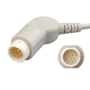
- Inspect all external ports and connectors for bent pins, corrosion, or debris
- Inspect power cord for fraying, kinks, or damaged plug — replace if jacket is compromised
- Inspect ventilation openings — clear of dust and not blocked
- Verify all labels are legible (serial number, safety markings, port identifiers)
- Check mounting hardware (wall arm, roll stand) for stability and secure fastening
For detailed cable-specific inspection techniques (continuity testing, insulation resistance, shielding integrity), see Medical Cable Inspection & Testing Methods.
Section 3: Electrical Safety Testing
- Ground continuity test (per IEC 62353:2014, clause 5.2) — should be <0.2Ω
- Earth leakage current — should be within manufacturer specifications (typically <300μA for Class I equipment per IEC 62353)
- Patient leakage current (applied parts) — typically <10μA for CF-rated parts, <100μA for BF-rated (per IEC 60601-1)
- Insulation resistance test if indicated by manufacturer protocol
- Document all test results with Safety Analyzer model and calibration date
💡 BMET Best Practice: Consistent use of a Safety Analyzer as a routine step in closing every PM is considered mandatory for maintaining regulatory approval. File all safety test results — deterioration in leakage current readings over time is often the earliest indicator of an emerging insulation breakdown. Reference: IEC 62353:2014, Recurrent Test and Test After Repair of Medical Electrical Equipment.
Section 4: Functional Testing by Parameter
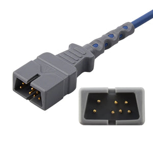
SpO2 Testing: Connect SpO2 sensor to patient simulator or use finger test. Verify SpO2 value (95–100% on healthy individual), pulse rate reading, and clean pleth waveform. Check that "sensor off" alarm triggers within 10 seconds of sensor removal. If troubleshooting SpO2 connector issues, the SpO2 connector pinout reference provides wiring diagrams by technology (Nellcor, Masimo, Philips FAST, Mindray).
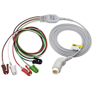
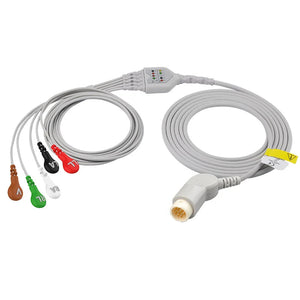
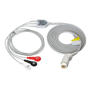
ECG Testing: Connect ECG cable to patient simulator. Verify heart rate accuracy (±2 bpm of simulator setting — typically test at 60, 80, 120 bpm). Verify respiration rate accuracy (±2 rpm). Test all lead configurations (3-lead, 5-lead, 12-lead as equipped). Verify arrhythmia detection on simulator patterns. For connector identification when replacing cables, see the ECG cable connector types identification guide.
NIBP Testing: Connect NIBP cuff and hose. Run NIBP leak test (wrap cuff on rigid cylinder; inflate to 200 mmHg; pressure should hold within 5 mmHg for 60 seconds). Test measurement on NIBP simulator at low (80/50), normal (120/80), and high (200/120) settings. Verify overpressure cutoff activates correctly. For hose connector compatibility when ordering replacements, see NIBP hose connector specifications.
Temperature Testing: Connect temperature probe to patient simulator set to 37°C and 40°C. Verify displayed value within ±0.2°C of simulator setting. Test both T1 and T2 channels if equipped. Important: Ensure the probe's thermistor type (YSI 400 or YSI 700 series) matches what the monitor expects — using the wrong type causes inaccurate readings or error codes. See YSI 400 vs 700 temperature probe comparison for compatibility details.
IBP Testing (if equipped): Connect IBP cable and pressure simulator. Verify zero calibration completes successfully. Apply known pressure values (0, 100, 200 mmHg) and verify displayed values within ±2 mmHg. Check waveform quality at simulated pulse rates. For cable pinout verification when troubleshooting intermittent IBP signals, see IBP cable pinout & signal specifications.
EtCO2 Testing (if equipped): Verify sidestream or mainstream sensor connectivity. Check water trap for discoloration or occlusion. Verify sampling line for kinks or moisture. Confirm reading accuracy with calibration gas if available.
Functional testing accuracy expectations are generally: ECG heart rate ±2 bpm, respiration ±2 rpm, temperature ±0.2°C, and IBP ±2 mmHg. SpO2 accuracy is sensor-dependent but should be within ±2–3% on a functional sensor with adequate perfusion. These tolerances are typical across Philips, GE, Mindray, and Dräger monitors — always confirm against the specific model's service manual.
Section 5: Alarm System Testing
- Verify high-priority alarm audio (continuous tone) and visual indicator (red) per IEC 60601-1-8
- Verify medium-priority alarm audio and visual indicator (yellow)
- Verify low-priority / advisory alarm (cyan or blue, depending on brand)
- Test alarm silence/pause function — confirm it re-engages after timeout period
- Verify nurse call relay output (if connected to nurse call system)
- Verify alarm limits can be adjusted and are retained after power cycle
- Test alarm escalation behavior if applicable (e.g., Philips IntelliVue alarm delay features)
Section 6: Battery Testing
- Record battery type (lead-acid or lithium-ion) and installation date
- Verify battery charges when AC power is connected (charge indicator active)
- Disconnect AC power; verify monitor operates on battery; record runtime
- Compare runtime to manufacturer specification — replace if runtime is <70% of rated capacity
- Perform battery optimization if due (every 3 months for lead-acid): full charge (>6 hours) → full discharge (disconnect AC, run until shutdown) → full recharge (>6 hours)
- Replacement guideline: lead-acid batteries approximately every 2 years; lithium batteries approximately every 3 years (per typical manufacturer service manuals)
⚠️ Battery Safety: Never allow liquids to enter the battery compartment. Manufacturer service manuals (Philips IntelliVue, GE CARESCAPE, Mindray BeneVision) specifically warn against liquid ingress into the monitor housing, power switches, connector interfaces, or ventilation openings during cleaning or battery replacement. Always power down and disconnect before battery service.
Section 7: Accessory Inspection
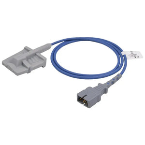
SpO2 sensors and cables: Check cable jacket for cuts or fraying; verify connector pins are straight and clean; test sensor emitter glow (faint red visible in dark room); replace if clip spring is weak or sensor housing is cracked.
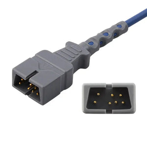
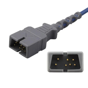
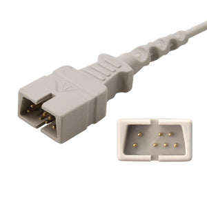
ECG cables and leadwires: Check trunk cable connector for bent pins; verify snap/clip/grabber electrode attachments for spring tension; inspect cable jacket along full length; check color coding is intact and legible. For connector type identification across brands, refer to the ECG cable connector types guide.
NIBP cuffs and hoses: Inspect cuff bladder for holes or delamination; check hose for kinks, cracks, or discoloration; verify connectors seat firmly; test for leaks.
Temperature probes: Check probe tip for damage; verify cable insulation; test thermistor resistance with multimeter — should match YSI 400 or 700 series specification for the probe type.
IBP cables: Inspect connector pins; verify cable shielding integrity; check for intermittent connections by gently flexing the cable while monitoring the signal. For electrical specifications, see IBP cable pinout & signal specifications.
EtCO2 water traps and sampling lines (if equipped): Replace water trap if discolored or partially occluded; check sampling line for kinks or moisture; verify airway adapter is clean.
🧹 Cleaning Note: Accessories should never be soaked in water or disinfectant solution, and cable connector pins must not get wet. Recommended disinfectants: 70% isopropyl alcohol or 70% ethanol applied with a soft cloth, followed by wiping with a damp cloth to remove residue. Excessive disinfection can accelerate cable jacket degradation — clean only as required by hospital infection control policy. Reference: Manufacturer cleaning guidelines per IEC 60601-1 clause 11.6.6.
Section 8: Software / Firmware
- Record current software revision (Main Setup → Revision → Software)
- Check manufacturer's website or service bulletins for available updates
- Verify network connectivity to central station (if applicable): check network cable, verify bed number assignment, confirm no IP conflicts
- Verify date and time synchronization
- Check configuration settings against department standards (alarm limits, default patient type, display layout)
For brand-specific monitor service tips, see our guides for Philips & GE monitors and Mindray monitors. For common error code interpretation, see patient monitor error codes troubleshooting.
Section 9: Post-PM Documentation
- Record all test results (pass/fail with measured values, not just checkmarks) — this is critical for Joint Commission EC.02.04.01 compliance
- Document any corrective actions taken
- Document any accessories replaced and the reason
- Apply PM completion sticker with date and technician ID
- Update CMMS with PM completion, next scheduled PM date, and any open issues
- If any test failed and was not corrected: tag device as "Out of Service" and create a corrective maintenance work order
For complete documentation requirements, retention timelines, and Joint Commission/CMS compliance details, see our dedicated BMET documentation & compliance record-keeping guide.
PM Tools Required
| Tool | Purpose | Notes |
|---|---|---|
| Electrical Safety Analyzer | Ground continuity, leakage current, insulation resistance per IEC 62353 | Must be calibrated; record analyzer S/N and cal date |
| Patient Simulator (multi-parameter) | ECG, respiration, temperature, IBP functional testing | Should provide configurable HR, RESP, TEMP, pressure values |
| NIBP Simulator / Pressure Source | NIBP accuracy verification and overpressure testing | Some monitors have built-in NIBP test modes |
| Digital Multimeter | Cable continuity, temperature probe resistance testing | Resistance mode for thermistor verification |
| Known-Good Accessories ("Hero Kit") | Swap testing during functional verification | Maintain verified accessories for PM use |
| Cleaning Supplies | 70% isopropyl alcohol, soft cloths, cotton swabs | For connector cleaning and surface disinfection during PM |
Accessory Quality and PM Intervals
Accessory quality directly affects PM outcomes and workload. Based on MedLinket's technical support data (N=12,400+ tickets across 2,000+ hospitals, 2022–2025), low-quality cables and sensors generate more false alarms, more "leads off" or "sensor off" errors, and more clinical complaints between PM cycles — all of which increase unplanned service calls and reduce BMET productivity.
Key quality indicators that impact PM performance:
ECG cables: Injection-molded connectors resist moisture and physical damage far better than glued assemblies. MedLinket's patented wide-mesh anti-dust cable sheaths (utility patent ZL2019XXXXXXX) prevent debris accumulation at cable terminations — a common source of intermittent signal failures that show up during PM. Electrode clips rated for 20,000+ cycles (exceeding IEC 60601-2-25/EC53 standard requirements) maintain spring tension longer, reducing false "leads off" events.
SpO2 sensors: Three-sided light-shielding design (sides plus back) in MedLinket finger-clip sensors reduces ambient light interference. Body-contoured cavity design ensures consistent LED-to-detector alignment. These design features directly reduce the frequency of "SpO2 searching" or "low signal quality" events between PM cycles.
NIBP cuffs: TPU material cuffs with welded bladders outperform nylon cuffs with sewn bladders in leak resistance over time. The artery index marker must remain clearly visible for correct placement — MedLinket reusable NIBP cuffs maintain legibility through repeated cleaning cycles.
Temperature probes: Consistent thermistor accuracy depends on manufacturing tolerance control (per YSI 400/700 series resistance–temperature curves). Probes that drift out of specification between PM cycles indicate poor manufacturing quality.
For a detailed accessory replacement timeline, see Patient Monitor Accessory Replacement Schedule. To evaluate whether compatible accessories meet your quality requirements, use our third-party accessory evaluation framework.
Need Quality Accessories for Your PM Program?
MedLinket provides ISO 13485-certified, FDA 510(k)-registered compatible accessories for Philips, GE, Mindray, Dräger, Nihon Kohden, and more. Every unit is 100% factory-tested before shipment. Free compatibility verification available.
Frequently Asked Questions
What is the standard PM interval for patient monitors?
Most manufacturers recommend annual PM at minimum. High-use environments (ICU, OR, transport) should have PM every 6 months. The Joint Commission standard EC.02.04.03 requires that accredited organizations maintain medical equipment based on a maintenance strategy. Some facilities use risk-based scheduling per AAMI EQ56, where critical care monitors receive more frequent inspections. Always check the specific manufacturer's service manual for model-specific requirements.
Do patient monitor accessories need PM testing?
Yes. Accessories are part of the measurement chain and should be inspected during every PM. Check cable insulation, connector integrity, sensor optics, cuff bladder condition, and probe resistance. Based on MedLinket's support data, a degraded accessory is the root cause in approximately 65–70% of monitor service calls (N=12,400+ tickets, 2022–2025) — meaning a monitor can fail functional testing even though the monitor hardware itself is fine. Include accessory inspection as a dedicated section of your PM checklist.
What tools are required for patient monitor PM?
Essential tools: an electrical safety analyzer (calibrated per IEC 62353), a multi-parameter patient simulator, an NIBP simulator or pressure source, a digital multimeter, known-good test accessories (a "hero kit"), and cleaning supplies (70% isopropyl alcohol, soft cloths). For advanced testing, a SpO2 simulator and an ECG simulator with arrhythmia waveforms are recommended. Record all tool serial numbers and calibration dates in your PM documentation.
How often should I condition the patient monitor battery?
Battery optimization (full charge → full discharge → full recharge) is generally recommended every 3 months for lead-acid batteries. Lead-acid batteries should be replaced approximately every 2 years; lithium batteries approximately every 3 years. Always record the battery installation date and conditioning cycle history. Refer to the specific monitor manufacturer's service manual — for example, Philips IntelliVue and GE CARESCAPE both have model-specific battery management procedures.
What is the difference between a PM checklist and a calibration procedure?
A PM checklist is the overall preventive maintenance workflow — it covers visual inspection, electrical safety, functional testing, accessory inspection, battery testing, and documentation as a complete scheduled procedure. Calibration is one component within that workflow, focused specifically on verifying measurement accuracy against known reference values (e.g., NIBP pressure accuracy, temperature accuracy, IBP zero/span verification). For detailed calibration schedules, procedures, and standard references, see our dedicated calibration requirements for patient monitor accessories guide.
How should I document PM results for Joint Commission compliance?
Record all measured test values (not just pass/fail checkmarks), corrective actions taken, accessories replaced with reasons, software revision verified, and safety test results including analyzer serial number and calibration date. Include technician ID and date. Update your CMMS with PM completion and the next scheduled date. The Joint Commission's EC.02.04.01 and EC.02.04.03 standards require that maintenance activities be documented and that the documentation demonstrate the equipment was tested and found safe and functional. For a complete guide to documentation requirements and retention timelines, see our BMET documentation & compliance record-keeping guide.
Related BMET Resources
This article is part of the MedLinket BMET Resource Hub — a complete technical library for biomedical equipment technicians covering troubleshooting, specifications, maintenance, and procurement guidance.
🔧 Same-Intent: Maintenance & Inspection
- Medical Cable Inspection & Testing Methods — visual, electrical, and safety check procedures for cables
- Calibration Requirements for Patient Monitor Accessories — calibration schedules, procedures, and standard references
📋 Upstream: Compliance & Standards
- BMET Documentation & Compliance Record-Keeping — what to record, how to organize it, and retention requirements
🛒 Downstream: Replacement & Procurement
- Patient Monitor Accessory Replacement Schedule — when to replace each accessory type
- BMET Cost-Saving Strategies for Accessories — how to extend PM-driven accessory lifespan and reduce spending
- How to Evaluate Third-Party Medical Accessories — decision framework for accessory product evaluation
🔍 Troubleshooting Guides (by Parameter)
- Patient Monitor Error Codes: BMET Troubleshooting Guide
- NIBP Measurement Errors Troubleshooting
- Temperature Probe Errors Troubleshooting
- IBP Transducer Troubleshooting
📐 Technical Specs & Compatibility
- SpO2 Connector Pinout Reference
- ECG Cable Connector Types Identification Guide
- NIBP Hose Connector Specifications
- YSI 400 vs 700 Temperature Probe Comparison
- Patient Monitor Accessory Compatibility Matrix
- Medical Cable Specifications: Shielding, Impedance & Materials
About MedLinket
MedLinket has manufactured patient monitoring accessories since 2004 — 21+ years of experience supporting PM programs at 2,000+ hospitals across 120+ countries. Certified: ISO 13485:2016, MDSAP, with 19 FDA 510(k) clearances, 48 EU CE Class II registrations, and 14 ANVISA registrations. Our full product line covers SpO2, ECG, NIBP, temperature, IBP, EtCO2, and EEG accessories — all 100% factory tested with product liability insurance up to $5 million.
Contact: marketing@med-linket.com | WhatsApp: +86 189 2972 7044 | 1-hour response