📚 Part of: BMET Resource Hub › Specs & Reference
Quick answer: a medical-grade patient monitor cable has to do three things well to meet IEC and FDA expectations — reject interference, survive years of cleaning and flexing, and stay electrically safe. When qualifying or inspecting one, verify three specifications:
- Shielding — spiral for flex (ECG/SpO₂), braided for broadband (IBP/trunk), or dual-layer for critical signal paths, per IEC 60601-1-2.
- Jacket — TPU outperforms PVC on chemical resistance, flex life and biocompatibility, per ISO 10993.
- Connector — injection-molded construction is sealed by design and outlasts glued or heat-shrink terminations in clinical use.
This page covers the material and construction requirements a BMET should check. For how to test them, see the companion cable inspection & testing methods guide.
📌 Scope: this page is a material & construction reference — what to look for when qualifying or evaluating patient monitor cables.
For inspection procedures (how to test), see medical cable inspection & testing methods. For parameter-specific pinouts, see SpO₂ connector pinout, ECG cable connector types, or IBP cable pinout specifications.

Why cable specifications matter clinically
The cable between a sensor and a patient monitor is not just a wire — it is a precision signal conduit that has to reject electromagnetic interference, survive thousands of cleaning cycles, last years of clinical use, and carry microvolt-level signals without distortion. When a BMET evaluates monitoring cables — for procurement, failure analysis or quality comparison — the underlying specifications are what separate a clean trace from a noisy one.

Poor cable quality is a hidden cause of many monitoring problems. Three common categories of ECG interference trace directly to cable construction, and all three relate to the EMC behaviour covered by IEC 60601-1-2:
| Interference type | Visible symptom | Cable-related root cause |
|---|---|---|
| AC mains (50/60 Hz) | Regular sinusoidal artifact on the ECG baseline | Inadequate shielding; broken shield conductor; poor grounding through the cable |
| Baseline wander / instability | Slow, irregular movement of the baseline | Unreliable electrode-to-cable connection; poor contact at connector pins; intermittent conductor |
| Electrosurgical (ESU) interference | High-frequency noise bursts during cautery | Insufficient shielding bandwidth; cables routed too close to ESU leads |
For troubleshooting these on specific monitors, see the patient monitor error codes troubleshooting guide. The pattern most experienced BMETs see in the field is consistent: when a unit complains about a "noisy ECG," the first things to check are shield continuity and jacket condition — generic economy cables with unshielded or thinly-shielded conductors are a frequent culprit. Shielding continuity and jacket material are baseline requirements, not premium features.
Applicable standards reference
Patient monitor cables must comply with several international standards. BMETs should reference these when qualifying new suppliers or weighing OEM vs compatible accessories. Always confirm the current edition of each standard before applying a pass/fail limit.
| Standard | Scope | Key cable requirements |
|---|---|---|
| IEC 60601-1 | General safety and essential performance of medical electrical equipment | Insulation (basic / supplementary / reinforced); creepage and clearance; dielectric strength; patient leakage-current limits |
| IEC 60601-1-2 | Electromagnetic compatibility (EMC) | Immunity levels for conducted and radiated interference; emission limits; shielding requirements derive from these immunity thresholds |
| IEC 62353 | Recurrent testing and testing after repair | Insulation resistance and protective-earth/leakage pass-fail criteria for in-service cables |
| ISO 10993 | Biological evaluation of medical devices | Biocompatibility of jacket and connector materials in patient contact: cytotoxicity, sensitisation, irritation |
| AAMI EC53 | ECG cables and leadwires | ECG-specific performance: defibrillation overvoltage protection; flex-life requirements; connector pull strength |
For a structured way to apply these to vendor selection, see the vendor qualification checklist. You can verify a manufacturer's clearances directly in the FDA 510(k) database — a step worth doing for any supplier, since registration counts and scope should be checked at the source rather than taken from marketing copy.
EMI shielding: types, performance & selection

Shielding is the single most important cable specification for signal quality. It determines how effectively external electromagnetic interference is kept off the signal conductors, and the required level derives from the immunity thresholds in IEC 60601-1-2.
| Shielding type | Construction | EMI rejection | Flex performance | Best for |
|---|---|---|---|---|
| Spiral (served) | Wire strands wrapped helically around conductors | Good for low frequency (50/60 Hz) | Excellent — holds up to repeated flexing | ECG cables, SpO₂ cables — frequent movement |
| Braided | Wire strands woven in an interlocking pattern | Better broadband (low + high frequency) | Good — slightly stiffer than spiral | IBP cables, trunk cables — less movement |
| Foil | Aluminium/Mylar foil wrap | Good high frequency; weak low frequency | Moderate — foil can crack with repeated flexing | Data cables; less common bedside |
| Dual-layer | Inner + outer shields (e.g. spiral + braided, or spiral + foil) | Best overall across frequencies | Good — inner handles flex, outer handles EMI | EEG adapter cables, critical signal paths |
💡 SpO₂ shielding note: SpO₂ sensors add a different strategy — three-sided optical shielding on the sensor tip (top, left, right) to block ambient light. That is optical noise control at the sensor, distinct from the electrical EMI shielding in the cable. For connector details, see the SpO₂ connector pinout reference.
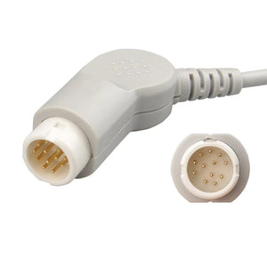
Shielding choice is a manufacturing decision, not a catalog afterthought. As one example from our own line, the specialty SpO₂ cable (internal series code DX0027A) is built with a dual-layer shield specifically to lower signal interference, while ECG and other specialty cables in the same family are offered in materials ranging from silicone and TPU to PVC depending on the flex and chemical environment. The principle holds across the industry: match the shield to the signal level and the EMI environment, then make sure it stays continuous through every connector.
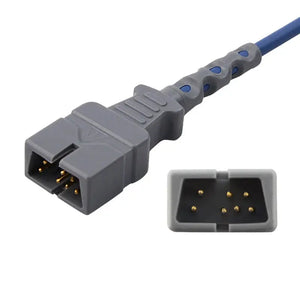
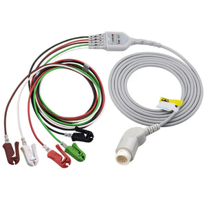
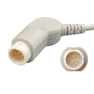
Philips-compatible ECG trunk cable (3-lead), M1500A
A spiral-shielded, TPU-jacketed trunk cable with an injection-molded connector — the construction this section recommends for movement-heavy ECG use. Defibrillation-protected to AAMI EC53; built to the EMC behaviour of IEC 60601-1-2.
Jacket materials: TPU vs PVC
The jacket determines chemical resistance, flex life, patient comfort and infection-control behaviour. Any material in patient contact has to meet ISO 10993 biocompatibility requirements first; after that, the TPU-vs-PVC choice is largely about service life.
| Property | TPU (thermoplastic polyurethane) | PVC (polyvinyl chloride) |
|---|---|---|
| Chemical resistance | Strong — handles 70% IPA, quaternary-ammonium and most hospital disinfectants without degrading | Moderate — some disinfectants cause surface cracking and stiffening over time |
| Flex life | Superior — keeps flexibility over extended use; low memory effect | Good initially, but stiffens with age and chemical exposure |
| Temperature range | Wider operating range and better cold flexibility | Narrower; becomes brittle in cold environments |
| Biocompatibility | Typically DEHP-free and latex-free per ISO 10993 | May contain DEHP plasticiser (a phthalate concern under EU REACH) |
| Infection control | Smoother surface; easier to clean; fewer micro-crevices for biofilm | Surface can develop micro-cracks that harbour pathogens |
| Cost | Higher material cost (offset by longer service life) | Lower material cost |
| MedLinket standard | Yes — TPU is standard across reusable ECG, SpO₂ and extension cables | Used in some economy-grade products |
Independent cable-engineering sources broadly agree that TPU is the preferred reusable patient-cable jacket for its abrasion resistance, wide temperature range and chemical tolerance. The common rule of thumb is that TPU delivers materially longer flex life than PVC — figures around 2–3× are widely cited, though the exact ratio depends on construction and use. For fleet-level cost analysis, see BMET cost-saving strategies: the higher TPU unit cost is typically offset by longer service life and fewer replacements.
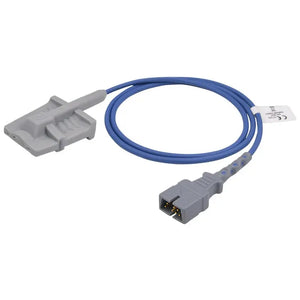
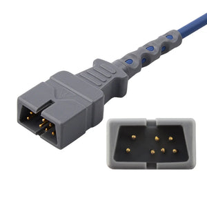
Nellcor-compatible short adult soft SpO₂ sensor, M1191T
A DEHP-free TPU-jacketed sensor designed to withstand repeated disinfectant exposure without stiffening; biocompatibility evaluated against ISO 10993. Compatible with the Nellcor OxiMax platform.
Connector construction: injection-molded vs alternatives
The connector is the most failure-prone part of any medical cable — it endures repeated mating cycles, cleaning-solution exposure, drops and cable tension. In MedLinket's field experience across hospital installations, connector and strain-relief failures account for a large share of cable-related service calls — more than conductor breaks in the cable body.

| Construction | Method | Durability | Waterproofing |
|---|---|---|---|
| Injection-molded (MedLinket standard) | Polymer encapsulates housing, pins and termination in one mold | Excellent — integral bond, no seams to separate | Excellent — sealed by design |
| Glued / cemented | Pre-formed housing glued to the cable after pin soldering | Moderate — adhesive degrades with cleaning chemicals | Limited — glue lines can crack; moisture ingress |
| Heat-shrink | Heat-shrink tubing over solder joints | Fair — adequate for low-stress use | Poor — not sealed against liquid |
Connector construction is a key evaluation criterion when comparing suppliers. For a structured approach, see the third-party accessory evaluation guide.
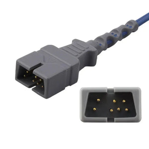
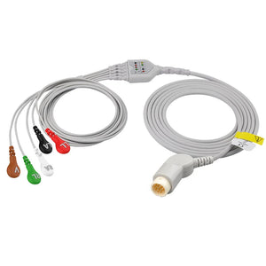
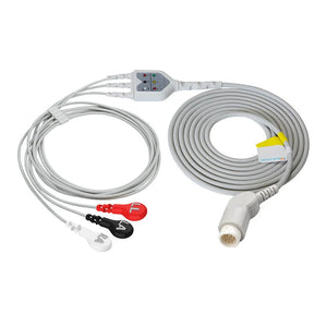
Philips-compatible direct-connect ECG cable (5-lead grabber), M1975A
A fully injection-molded connector with integral strain relief — sealed by design, on a spiral-shielded TPU cable — for Philips IntelliVue-series monitors. The construction this section recommends for high-handling environments.
Impedance and electrical requirements
Cable electrical specifications have to match the parameter's signal characteristics. The limits below derive from IEC 60601-1 (insulation and safety), IEC 62353 (in-service testing) and parameter-specific standards. Treat the figures as typical reference values and confirm against the current standard edition and the device IFU.

| Electrical parameter | Typical requirement | Standard / source |
|---|---|---|
| Insulation resistance | ≥ 2 MΩ at 500 VDC (each conductor to shield) | IEC 62353 (recurrent-test pass/fail) |
| Dielectric strength | Higher for reinforced than basic insulation (type test) | IEC 60601-1 §8.8 |
| Conductor resistance | < 1 Ω per conductor, end-to-end (typical lengths) | Manufacturing spec; verified per IEC 62353 |
| Shield continuity | < 1 Ω from shield to ground pin at connector | Manufacturing spec; critical for EMI rejection |
| Patient leakage current | Within Type CF / BF applied-part limits | IEC 60601-1 §8.7; verified per IEC 62353 |
| Defibrillation protection | ECG cables must survive defibrillation pulses without damage | AAMI EC53; IEC 60601-2-25 |
For the full measurement methodology, see the medical cable inspection & testing methods guide. For testing frequency and intervals, see calibration requirements for patient monitor accessories.
Parameter-specific cable requirements
Different monitoring parameters put different demands on cable construction. The signal levels below show why shielding and connection quality matter more for some parameters than others.

| Parameter | Signal level | Critical cable spec | Key risk |
|---|---|---|---|
| ECG | ~0.5–5 mV | Shielding effectiveness; defibrillation protection; flex life (AAMI EC53) | 50/60 Hz mains pickup; ESU interference; connector intermittence |
| SpO₂ | Analog: low-level; digital: protocol-dependent | Optical shielding at sensor; cable shielding for analog; data integrity for digital | Ambient light at sensor; EMI on analog signal; motion artifact |
| IBP | ~5 µV/V/mmHg (very small) | Shield continuity; low contact resistance; impedance matching | Noise from a broken shield; connector corrosion; signal drift |
| Temperature | Resistance-based (thermistor) | Low cable-resistance contribution; consistent contact resistance (YSI 400/700) | Cable resistance adding to the reading; intermittent connector contact |
For parameter-specific connector details, see: ECG cable connector types · SpO₂ connector pinout · IBP cable pinout specifications · YSI 400 vs 700 temperature probes. For cross-brand fit, see the patient monitor accessory compatibility matrix.
🎯 Qualifying compatible cables across parameters?
A common approach is to pilot one representative cable per parameter (ECG, SpO₂, IBP, temperature) on one or two beds for 30–60 days before fleet-wide procurement. MedLinket can supply matching compatible cables for that kind of evaluation, with spec sheets and certification documents for each.
ECG cables SpO₂ cables IBP cables Request evaluation samples & spec sheets
Key specifications for cable inspection
When inspecting cables during preventive maintenance, verify the items below. For full procedures, see the cable inspection & testing methods guide, and document results per your BMET documentation and compliance procedures.
| What to check | Pass criteria | Reference |
|---|---|---|
| Jacket integrity — no cracks, kinks, discolouration or stiffening | No visible damage; jacket flexible and smooth | Visual, IEC 62353 |
| Connector housing — no cracks, deformation or loose pins | Firm click/lock; no wobble; pins clean and aligned | Visual, IEC 62353 |
| Conductor continuity (each pin, end-to-end) | < 1 Ω per conductor | IEC 62353 |
| Insulation resistance | ≥ 2 MΩ at 500 VDC, each conductor to shield | IEC 62353 |
| Shield continuity | < 1 Ω from shield to ground pin | Manufacturing spec |
| Strain relief | No separation between cable and connector; no exposed conductors | Visual, IEC 62353 |
Need patient monitor cables built to these specs?
MedLinket manufactures compatible patient monitor cables with TPU jackets, injection-molded connectors and spiral or dual-layer shielding — ISO 13485 certified, FDA 510(k) cleared, factory-tested. To weigh whether compatible cables fit your facility's requirements, start with the OEM vs compatible parts analysis.
Frequently asked questions
What type of shielding is best for ECG cables?
Spiral (served) shielding is most common for ECG cables because it gives good 50/60 Hz mains-interference rejection while keeping excellent flex performance — the Philips M1500A-compatible trunk cable is one example, using spiral shielding with a TPU jacket. For environments with heavy electrosurgical interference (operating rooms), dual-layer shielding gives better broadband rejection per IEC 60601-1-2. Whatever the type, the shield must stay continuous through every connector — a break anywhere nullifies the cable's EMI rejection.
What is the difference between TPU and PVC cable jacket materials?
TPU offers stronger chemical resistance to hospital disinfectants, longer flex life (commonly cited at roughly 2–3× that of PVC), a wider temperature range, and is typically DEHP-free per ISO 10993. PVC costs less but stiffens with age and can crack under repeated disinfectant exposure. TPU is the preferred jacket for reusable patient monitor cables under current infection-control practice. See the TPU vs PVC table above.
What IEC standards apply to patient monitor cables?
The primary ones are IEC 60601-1 (general safety: insulation, leakage current, dielectric strength), IEC 60601-1-2 (EMC: immunity and emission limits), IEC 62353 (recurrent testing for in-service cables) and ISO 10993 (biocompatibility of patient-contact materials). AAMI EC53 adds ECG-specific requirements for defibrillation protection and flex life. See the standards table.
How do I verify cable shielding effectiveness during inspection?
Measure shield continuity end-to-end with a multimeter — resistance should be under 1 Ω from the shield termination at one connector to the ground/shield pin at the other. A broken or intermittent shield shows high or fluctuating resistance. For the full protocol, see the cable inspection & testing methods guide.
Why do injection-molded connectors last longer than glued connectors?
An injection-molded connector encapsulates the termination, solder joints and housing in a single sealed polymer structure — a watertight, mechanically integral bond with no seams or adhesive to degrade — such as the Philips M1975A 5-lead cable. Glued connectors rely on adhesive bonds that break down under cleaning chemicals, mechanical stress and temperature cycling, so they tend to fail earlier in clinical use.
What insulation resistance should a medical cable maintain?
Per IEC 62353, the minimum insulation resistance for applied parts (including patient monitor cables) is 2 MΩ tested at 500 VDC. New cables typically measure well above 20 MΩ. A reading below 2 MΩ indicates degradation and the cable should be removed from service. Test during preventive maintenance or whenever cable damage is suspected, following the current edition of the standard.
Related BMET resources
About MedLinket
MedLinket (Shenzhen Med-link Electronics Tech Co., Ltd, est. 2004) manufactures compatible patient monitor cables, sensors and accessories from its own R&D centre, mold workshop and medical-cable extrusion lines. Reusable cables use TPU jackets and injection-molded connectors as standard. The company is ISO 13485:2016 certified, FDA 510(k) cleared, CE marked and MDSAP audited, and supplies more than 2,000 hospitals across over 110 countries, with up to USD 5M product-liability coverage.
Contact: marketing@med-linket.com · WhatsApp