📚 Part of: BMET Resource Hub › Specs & Selection
Quick Answer: This reference covers IBP cable pinout configurations, excitation voltage requirements, and signal output ranges for major patient monitor brands — including Philips, GE, Mindray, Dräger, Nihon Kohden, and Datascope — helping BMETs verify cable integrity, identify transducer connector compatibility, and diagnose signal-level faults.
📌 Article Scope: This page provides electrical specifications and wiring reference for IBP cables and the standardized transducer interface.
For clinical troubleshooting of IBP waveform problems (damped traces, drift, zeroing failures), see our IBP transducer troubleshooting guide. For cross-brand accessory compatibility, see the multi-brand compatibility matrix.

How IBP Signal Transmission Works
Understanding the IBP signal chain is essential for diagnosing cable-level faults. The invasive blood pressure measurement system consists of three electrical stages connected by the IBP cable, operating in accordance with IEC 60601-2-34 (particular requirements for invasive blood pressure monitoring equipment) and the transducer interface standard ANSI/AAMI BP22.
Stage 1 — Excitation: The patient monitor supplies an excitation voltage (the BP22 interface accepts 4–8 V, most commonly 5 V) through the IBP cable to power the transducer's Wheatstone bridge circuit. This excitation voltage is critical — an incorrect voltage produces proportionally incorrect pressure readings.
Stage 2 — Transduction: The disposable pressure transducer converts mechanical pressure (from the fluid column connected to the arterial catheter) into a proportional electrical signal. The Wheatstone bridge inside the transducer produces a differential millivolt output that varies linearly with applied pressure. Under ANSI/AAMI BP22, the long-standing industry-standard transducer sensitivity is 5 µV/V/mmHg — 5 microvolts of output per volt of excitation per mmHg of applied pressure.

Stage 3 — Signal return: The transducer's differential output signal travels back through the IBP cable to the monitor's signal amplifier, which converts the millivolt signal into a calibrated pressure display in mmHg. For a standard 5 µV/V/mmHg transducer at 5 V excitation, the output works out to roughly 2.5 mV at 100 mmHg, scaling linearly with pressure.
💡 Key BMET Insight: Because signal levels are in the microvolt-to-millivolt range, IBP cables are highly sensitive to shielding quality, connector corrosion, and intermittent connections. A problem invisible in a 5 V digital signal can cause significant pressure-reading errors in a millivolt IBP signal. This is why cable-level inspection is critical — see our medical cable shielding and impedance specifications for detailed requirements.
The AAMI BP22 Transducer Interface
Regardless of brand or connector type, most modern disposable IBP transducers are built to conform to the ANSI/AAMI BP22 interface so they remain interchangeable across monitors. The values below are the published standard's interface characteristics — useful as the reference point against which you test any cable-and-transducer combination. (Always confirm a specific transducer's labeled values against its own instructions for use; manufacturers may add series resistance to standardize sensitivity, and exact figures can vary by model.)
| Parameter | AAMI BP22 Interface Value | Reference |
|---|---|---|
| Excitation voltage | 4–8 V (5 V most common) | ANSI/AAMI BP22 |
| Sensitivity | 5 µV/V/mmHg (industry standard; most transducers ±1% per BP22) | ANSI/AAMI BP22 |
| Excitation (input) impedance | > 200 Ω (DC to 5 kHz) | ANSI/AAMI BP22 |
| Signal (output) impedance | < 3000 Ω (DC to 5 kHz) | ANSI/AAMI BP22 |
| Zero balance | within ±75 mmHg (corrected by zeroing) | ANSI/AAMI BP22 |
| Pressure range (arterial) | −30 to +300 mmHg (typical clinical use) | IEC 60601-2-34 |
| Worked example (output) | ≈ 2.5 mV at 5 V excitation, 100 mmHg | Calculated from sensitivity |
Why these numbers matter for cable diagnosis: When you measure bridge resistance across the transducer connector pins and get a value outside the expected range (open circuit, near-zero, or asymmetric between the excitation and signal pairs), the fault is in the transducer, cable, or connector — not the monitor. This is the first electrical test when an IBP channel shows "transducer disconnected" or gives erratic readings. Note that frequency response and overall measurement accuracy are governed by the whole fluid-filled catheter system (tubing, flush device, air bubbles) far more than by the cable, so cable testing isolates the electrical path specifically.
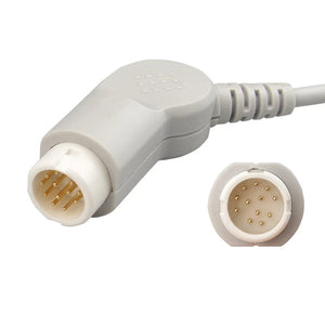
IBP Transducer Connector Families
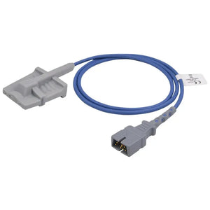
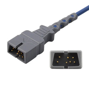
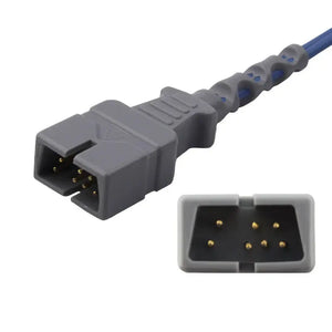
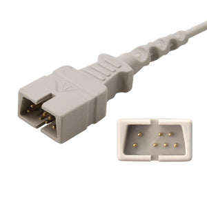
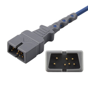
There are six major transducer connector families in clinical IBP monitoring. These connectors are not interchangeable — using the wrong cable-to-transducer connector results in no signal or incorrect readings. (Brand names are referenced for compatibility identification only and imply no OEM or endorsement relationship.)

| Transducer Family | Pin Count | Common Monitor Brands | MedLinket Product |
|---|---|---|---|
| Abbott / Medex | 6-pin round | Philips, GE, Mindray, Dräger | Abbott 6-pin |
| Edwards | 5-pin | Philips, GE, Dräger | Edwards 5-pin |
| UTAH Medical | 4-pin | Philips, Mindray, Nihon Kohden | UTAH 4-pin |
| BD / Ohmeda | 7-pin | Philips, Nihon Kohden | BD 7-pin |
| B.Braun | 4-pin | Philips, Mindray, Nihon Kohden | B.Braun 4-pin |
| Argon / Maxxim | 5-pin | GE, Mindray, Dräger | Argon 5-pin |
| PVB / Simms | 5-pin | Various European | PVB 5-pin |
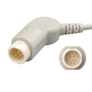
Philips IBP Cable Pinout
Philips monitors (IntelliVue MX, MP series) use a proprietary IBP connector. For complete Philips service info, see the Philips & GE monitor service guide.
| Transducer End | MedLinket Part | Key Pins |
|---|---|---|
| Abbott / Medex | 42661-27 | Exc+, Exc−, Sig+, Sig−, Shield, ID |
| Edwards | 896083021 | Exc+, Exc−, Sig+, Sig−, Shield |
| UTAH | 650-206 | Exc+, Exc−, Sig+, Sig− |
| BD | 684081 | Exc+, Exc−, Sig+, Sig−, Shield, Cal, ID |
| B.Braun | M1634A | Exc+, Exc−, Sig+, Sig− |
| Argon | Argon 12ft | Exc+, Exc−, Sig+, Sig−, Shield |
| Antmed | ACE-PT-01 | Exc+, Exc−, Sig+, Sig−, Shield |
GE Healthcare IBP Cable Pinout
GE monitors (CARESCAPE, Solar, Dash) use an 11-pin proprietary IBP connector. Dual-channel configurations are available.
| Transducer End | MedLinket Part | Notes |
|---|---|---|
| Abbott | 2021196-001 | Single-channel |
| Edwards (dual) | 2021197-003 | Dual-channel |
| UTAH | 700078-001 | Single-channel |
| BD | 684102 | Single-channel |
| Argon | 11-pin to Argon | Single-channel |
| B.Braun | 11-pin to B.Braun | Single-channel |
| Dual adapter | 2005772-001 | Dual adapter 0.3m |
| AAMI adapter | 2021197-001 | 11-pin to AAMI 6-pin |
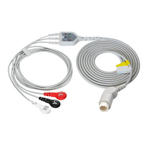
Mindray / Datascope IBP Cable Pinout
Mindray monitors (iMEC, iPM, BeneView) and legacy Datascope share compatible IBP interfaces. See Mindray monitor technical resources.
| Transducer End | MedLinket Part | Notes |
|---|---|---|
| Edwards | 0010-21-12179 | Direct |
| UTAH | 650-206M | Direct |
| Abbott | 001C-30-70759 | Direct |
| BD | 001C-30-70757 | Direct |
| Argon | Argon 12ft | Direct |
| B.Braun | B.Braun 12ft | Direct |
| Extension | 040-001029-00 | Double-end extension |
| Adapter | 001C-30-70758 | To AAMI interface |
Dräger IBP Cable Pinout
Dräger monitors (Infinity, Vista) use dedicated IBP connectors. Verify the monitor model before ordering — older models may differ.
| Transducer End | MedLinket Part |
|---|---|
| Abbott | MS22535 |
| Edwards | MS22147 |
| UTAH | MS22534 |
| BD | MS22148 |
| Argon | Dräger-Argon |
| B.Braun | Dräger-B.Braun |
| Adapter | 5731281 |
Nihon Kohden IBP Cable Pinout
Nihon Kohden (BSM, Life Scope series) monitors use proprietary IBP connectors. For additional compatibility, see the compatibility matrix.
| Transducer End | MedLinket Part |
|---|---|
| Edwards | JP-902P |
| UTAH | NK-UTAH |
| Abbott | NK-Abbott |
| BD | JP-900P |
| B.Braun | NK-B.Braun |
AAMI Standard 6-Pin IBP Interface
The AAMI 6-pin interface (per ANSI/AAMI BP22) is a standardized connector arrangement that lets a monitor-side adapter cable interface with any transducer brand through a common pin assignment.

| Pin | Function | Description |
|---|---|---|
| 1 | Exc + | Positive excitation to bridge |
| 2 | Sig + | Positive signal output |
| 3 | Sig − | Negative signal output |
| 4 | Exc − | Negative excitation (return) |
| 5 | Shield | Cable shield / ground |
| 6 | ID / Cal | Transducer ID or calibration (optional) |
MedLinket AAMI cables: 42661-14 · 650-208 · Edwards AAMI · Argon AAMI · B.Braun AAMI
Direct IBP Cables vs Adapter Cables
For cost optimization, see BMET cost-saving strategies.

| Factor | Direct Cable | Adapter System |
|---|---|---|
| Signal | Fewer connection points — optimal integrity | Extra junction — potential noise source |
| Inventory | One per monitor × transducer combo | Fewer total SKUs |
| Flexibility | Locked to one transducer brand | Swap transducer brands easily |
| Best for | Standardized facilities | Multi-brand or transitioning facilities |
IBP Cable Testing Procedures
For comprehensive testing aligned with IEC 62353, see our medical cable inspection guide. Document results per BMET documentation procedures.
| Test | Procedure | Pass Criteria |
|---|---|---|
| Visual | Inspect jacket for cuts, kinks. Check pins for corrosion. | No damage; pins clean/straight |
| Continuity | Multimeter pin-to-pin check | <2 Ω each pin; no opens |
| Bridge resistance | Measure Exc+/Exc− and Sig+/Sig− with transducer attached | Within transducer's labeled range; both pairs symmetric (within ~10%) |
| Short check | Check for continuity between excitation/signal/shield groups | >1 MΩ between non-connected pairs |
| Shield | Shield pin to cable shield; isolated from signals | <2 Ω shield; >1 MΩ to signals |
| Flex test | Monitor continuity while flexing at junctions | No intermittent faults — #1 cause of erratic IBP |

Include this in your patient monitor PM checklist. For IBP calibration, see calibration requirements.
Need Replacement IBP Cables or Transducers?
MedLinket manufactures compatible IBP cables, adapter cables, and disposable transducers for all major monitor brands — ISO 13485 certified, FDA 510(k) cleared, 100% factory tested. See our third-party evaluation guide and vendor qualification checklist.
Frequently Asked Questions
What excitation voltage do IBP transducers require?
The ANSI/AAMI BP22 transducer interface accepts 4–8 V, with 5 V most common across Philips, GE, Mindray, and Dräger monitors. An incorrect excitation voltage produces proportionally inaccurate readings, so it is one of the first things to verify on an IBP channel fault.
Are IBP transducer connectors interchangeable?
No. Each family (Abbott, Edwards, UTAH, BD, B.Braun, Argon) uses different pin counts and pinouts. The wrong connector means no signal or incorrect readings. See the connector families table or the compatibility matrix.
What is the standard signal sensitivity?
Under ANSI/AAMI BP22 the industry-standard transducer sensitivity is 5 µV/V/mmHg. At 5 V excitation and 100 mmHg, a standard transducer outputs about 2.5 mV, which the monitor's amplifier converts to a calibrated pressure display.
How do I test an IBP cable?
Multimeter pin-to-pin continuity, a bridge-resistance check across the excitation and signal pairs, short-circuit verification between non-connected pairs, and a flex/wiggle test at the connectors. See the cable testing procedures and our inspection guide.
Direct cable vs adapter cable — which should I use?
Direct = single cable, fewer junctions, locked to one transducer brand. Adapter = AAMI 6-pin interface, swap transducer cables freely, one more connection point. See the comparison table.
Why does IBP drift after zeroing?
Usually cable-level: dirty or corroded pins, damaged shielding, or a faulty transducer. Inspect per this guide's procedures, then see IBP transducer troubleshooting for systematic clinical diagnosis.
Related BMET Resources
About MedLinket
MedLinket (est. 2004) manufactures compatible IBP cables, IBP adapter cables, and disposable IBP transducers for all major monitor brands, covering the common transducer connector families. The company operates a dual-factory footprint (Shenzhen and Shaoguan) with more than 2,800 in-house molds and over 10,000 product types, is certified to ISO 13485:2016 with MDSAP coverage, and its products are FDA 510(k) cleared and CE marked under the EU MDR. MedLinket serves 2,000+ hospitals across 110+ countries, with product-liability insurance providing coverage up to USD 5 million. (Monitor brand names are referenced for compatibility only and imply no OEM or endorsement relationship.)
Contact: shopify@medlinket.com · WhatsApp