📌 Article Scope — IBP Clinical Troubleshooting & Diagnosis
- This guide covers IBP transducer troubleshooting — diagnosing zeroing failures, damped waveforms, signal drift, and transducer membrane problems.
- For IBP cable electrical specs, connector pinouts, and signal verification, see IBP cable pinout and signal specifications.
- For general patient monitor error codes across all parameters, see patient monitor error codes troubleshooting.
- For pressure infusion bag usage and setup, see what is a pressure infusion bag and what is it used for.
Table of Contents
- IBP Measurement System: Understanding the Signal Chain
- Common IBP Error Messages and Root Causes
- The Square Wave Test (Fast-Flush Test)
- Isolating Cable vs. Transducer vs. Module Faults
- IBP Connector Compatibility Reference
- Color-Coded Tubing: Reducing IBP Line Errors
- Frequently Asked Questions
- Related BMET Resources

IBP (Invasive Blood Pressure) troubleshooting is more complex than any other patient monitor parameter because the signal chain extends from the patient's artery through a fluid-filled catheter system to the electronic transducer and cable. When a BMET receives a call about IBP issues — zeroing failure, waveform damping, or pressure drift — the fault could be anywhere in this chain.
This guide provides a systematic framework for diagnosing IBP transducer errors, performing the square wave test, isolating cable vs. transducer vs. module faults, and understanding the fluid dynamics principles that underlie most IBP signal quality problems.
IBP Measurement System: Understanding the Signal Chain
Understanding the complete IBP signal chain is essential for localizing faults. Per ANSI/AAMI BP22:2019, the invasive pressure monitoring system consists of:
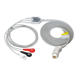
Signal chain: Patient intravascular pressure → Catheter → Pressure tubing + stopcocks → Pressure transducer (converts mechanical pressure to electrical signal) → IBP cable → Monitor module → Numeric + waveform display

The key components of a disposable pressure transducer system and their troubleshooting relevance:
| Component | Function | Troubleshooting Relevance |
|---|---|---|
| Drip chamber | Receives heparinized saline from infusion bag | Check fluid level; empty chamber = air enters system |
| Flush valve | Continuous flush at 3 ml/h; rapid flush at ~1 ml/s for square wave test | Blocked valve = inability to flush; defective valve = failed square wave test |
| Pressure transducer | Silicon piezoresistive sensor converts pressure to electrical signal | Core measurement component; sensitivity ±2% per ANSI/AAMI BP22; zero-drift-free design |
| Stopcocks (3-way) | Control fluid path direction — OFF points to the closed port | #1 cause of zeroing failures: stopcock in wrong position |
| Pressure tubing | Rigid-wall tubing transmits pressure signal without attenuation | Must be stiff and short; air bubbles or kinks degrade signal |
| Blood sampling reservoir | Temporarily stores heparin-saline/blood mixture for waste-free blood sampling | Fully enclosed design prevents microbial contamination (FDA-recommended for infection control) |
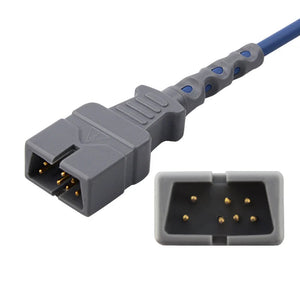
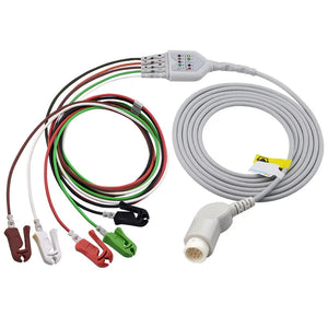
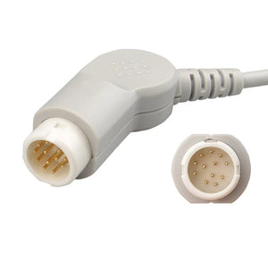
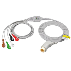
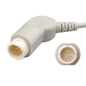
| Cable connector | Electrical interface to monitor | Must match monitor brand; 7 industry-standard interfaces (Abbott, UTAH, Edwards, BD, Argon, B.Braun, PVB) |
Common IBP Error Messages and Root Causes
The following table maps the most frequently encountered IBP error messages and symptoms to their root causes and recommended BMET actions. For error codes across all monitor parameters, see the patient monitor error codes master guide.
| Error / Symptom | Meaning | Most Likely Cause | BMET Action |
|---|---|---|---|
| IBP UNABLE TO ZERO | Zero calibration could not complete | Stopcock not open to atmosphere; air bubble on transducer dome; IBP cable fault; residual pressure in system | Verify stopcock position; remove cap and open to air; flush to remove bubbles; swap cable |
| IBP SIGNAL OUT OF RANGE | Pressure value exceeds valid measurement window | Transducer failure; massive air in system; cable open circuit; transducer not leveled | Check transducer level relative to phlebostatic axis; replace transducer; swap cable |
| Damped / flattened waveform | Waveform loses detail — absent dicrotic notch, slurred upstroke, narrow pulse pressure | Air bubbles in tubing; clotted catheter tip; kinked tubing; loose connection; low pressure bag (<300 mmHg) | Perform square wave test; flush system; check all connections; verify pressure bag at 300 mmHg |
| Over-ringing / noisy waveform | Waveform shows excessive oscillation — falsely high systolic, falsely low diastolic | Underdamped system: excessively stiff or long tubing, catheter whip, resonance | Square wave test confirms underdamping; shorten tubing; reduce stopcocks; consider damping device |
| Pressure drift (gradual offset) | Readings shift progressively without patient change | Transducer failure (rare with quality transducers); cable damage; temperature effect on transducer | Re-zero; if drift recurs quickly, swap transducer; if still drifts, swap cable; then suspect module |
| No waveform — flat line | No pressure signal detected | Cable disconnected; transducer not connected to catheter; stopcock fully off to patient; catheter occluded | Check entire signal chain connection by connection; verify stopcock positions |
The Square Wave Test (Fast-Flush Test)
The square wave test is the single most important diagnostic tool for IBP waveform quality. It evaluates the dynamic response (damping coefficient and natural frequency) of the entire fluid-filled measurement system in seconds, as described in ANSI/AAMI BP22:2019 §5.3.3 and standard hemodynamic monitoring textbooks.

How to Perform
- Ensure the pressure infusion bag is inflated to 300 mmHg
- Activate the flush valve by pulling the tab (or pressing, depending on design) for 1–2 seconds — this forces flush solution through the system at ~1 ml/s
- Release the flush valve abruptly
- Observe the waveform on the monitor:
| Waveform Pattern After Release | Interpretation | Clinical Impact | Action |
|---|---|---|---|
| Sharp rise, flat plateau, sharp drop, 1–2 small oscillations, then normal waveform | Optimally damped (correct) | Systolic and diastolic pressures are accurate | No action needed — system is performing correctly |
| Sluggish rise, rounded plateau, slow return, no oscillations | Overdamped | Systolic underestimated; diastolic overestimated; pulse pressure falsely narrow | Check for air bubbles; flush system; check catheter patency; verify pressure bag at 300 mmHg; check for loose connections |
| Sharp rise, sharp drop, then 3+ oscillations bouncing above and below baseline | Underdamped | Systolic overestimated; diastolic underestimated; "ringing" artifact | Shorten tubing; reduce number of stopcocks; check for catheter whip; consider inline damping device |
Isolating Cable vs. Transducer vs. Module Faults
When the square wave test and flush cannot resolve the issue, use this systematic isolation approach.

Each step is designed to rule out one component of the signal chain, following the principle recommended in IEC 62353 for systematic medical equipment fault diagnosis:
| Step | Action | If Problem Resolves | If Problem Persists |
|---|---|---|---|
| 1 | Replace the disposable transducer with a new unit | Original transducer was defective → discard | Problem is in the cable or module → go to step 2 |
| 2 | Replace the IBP cable with a known-good cable | Original cable was defective → retire cable | Problem is in the monitor module → go to step 3 |
| 3 | Test on a different IBP channel (if dual-channel monitor) or a different monitor | Original channel/module is faulty → escalate to service | Unlikely — reassess from step 1 with verified components |
Need IBP Cables or Transducers?
MedLinket manufactures compatible IBP cables and disposable pressure transducers for all 7 industry-standard interfaces and all major monitor brands. Fully enclosed blood collection reservoir with PTFE bacterial filtration. ±2% sensitivity per ANSI/AAMI BP22, zero-drift-free performance. ISO 13485 & FDA 510(k) certified.
IBP Connector Compatibility Reference
IBP uses one of the most standardized connector systems in patient monitoring. Seven industry-standard transducer interfaces are used across virtually all monitor brands. Unlike SpO2 (which has competing technology protocols) or ECG (which has brand-specific monitor connectors), IBP transducer-side interfaces are universal — the same Abbott transducer works with any monitor, provided you have the correct IBP cable for your monitor brand.
For IBP cable electrical specifications, pinout diagrams, and signal verification procedures, see our dedicated IBP cable pinout and signal specifications guide.
| Interface | Connector Type | MedLinket Transducer | MedLinket Cable (Philips) |
|---|---|---|---|
| Abbott | RJ11-6P6C Jack (round 6-pin) | Abbott transducer | Philips-Abbott cable |
| UTAH | DIN 1.5 Plug (4-pin) | UTAH transducer | Philips-UTAH cable |
| Edwards/Baxter | Round 5-pin Plug | Edwards transducer | Philips-Edwards cable |
| BD/Ohmeda | Round 7J Plug | BD/Ohmeda transducer | Philips-BD cable |
| Argon/MAXXIM | Round 5-pin Plug | Argon transducer | Philips-Argon cable |
| B.Braun | AJ Plug (4-pin) | B.Braun transducer | Philips-B.Braun cable |
| PVB/SIMMS | Round 5-pin Plug | PVB/SIMMS transducer | Contact for cable options |
IBP cables for GE, Mindray, Nihon Kohden, Dräger, and Biolight are also available — each with the same transducer-side interface options but a different monitor-side connector. For complete cross-brand lookup, see the multi-brand compatibility matrix. For brand-specific cable part numbers, see the Philips & GE monitor service guide or Mindray monitor technical resources.
MedLinket IBP transducers feature a fully enclosed blood sampling reservoir with PTFE bacterial filtration membrane that prevents microbial contamination during blood sampling — addressing an infection control concern identified in FDA guidance documents for invasive pressure monitoring systems. The screw-cap design prevents air entry into the vascular system, and the stored heparin-saline/blood mixture can be returned to the patient after sampling, reducing blood waste.
Color-Coded Tubing: Reducing IBP Line Errors
In complex ICU setups with multiple pressure lines (arterial, CVP, PA, ICP), connecting the wrong line to the wrong port is a documented patient safety risk. Wrong-line medication administration through arterial catheters is classified as a "never event" by patient safety organizations.
MedLinket IBP transducers use color-coded pressure tubing — red tubing for arterial lines — to visually distinguish arterial from venous (CVP), pulmonary artery, and other infusion lines. This simple visual identification system is consistent with The Joint Commission's National Patient Safety Goal on improving the safety of clinical alarm management and line identification.
This is one of five core MedLinket IBP differentiators alongside the enclosed blood reservoir, high-quality flush valve with consistent 3 ml/h flow rate, sampling stopcock with medical-grade silicone material, and compact mounting panel design that reduces ICU clutter. For a full quality comparison framework between OEM and compatible IBP components, see our OEM vs compatible parts analysis.
Frequently Asked Questions
Why can't I zero the IBP transducer?
The most common cause is incorrect stopcock position — the stopcock must be turned OFF to the patient (handle pointing toward patient) and the cap removed so the transducer is open to atmosphere. Other causes: air bubble trapped on the transducer dome preventing a stable zero reading, residual pressure in the system, or a faulty IBP cable. Verify stopcock position first, then flush to remove bubbles, then swap the cable if the problem persists.
What causes a damped arterial waveform?
Overdamping — the most common waveform quality issue — is caused by air bubbles in the tubing, a partially clotted catheter tip, kinked or compliant tubing, loose connections, or a pressure infusion bag below 300 mmHg. An overdamped waveform underestimates systolic and overestimates diastolic pressure, while MAP remains relatively accurate. Perform a square wave test to confirm, then flush the system, check all connections, and verify the pressure bag.
How do I know if the drift is from the cable or the transducer?
Isolate systematically: re-zero the system. If the reading drifts back within minutes, replace the transducer first. If drift continues with a new transducer, swap the cable. If drift still continues, the monitor module's IBP input channel may be faulty. MedLinket transducers use U.S.-sourced silicon piezoresistive sensors designed for zero-drift-free performance per ANSI/AAMI BP22 requirements — persistent drift with a new MedLinket transducer strongly suggests the issue is in the cable or module, not the transducer.
Are Abbott and UTAH transducer connectors interchangeable?
No. Abbott uses a round 6-pin (RJ11-6P6C) connector while UTAH uses a DIN 1.5 4-pin plug. They are physically different and cannot be cross-connected. Each transducer interface requires a matching IBP cable on the monitor side. If your hospital standardizes on one transducer type (e.g., Edwards), you need Edwards-compatible IBP cables for each monitor brand in your fleet. For detailed connector pinout information, see our IBP cable pinout and signal specifications guide.
How often should the IBP system be re-zeroed?
Re-zero whenever: the transducer is repositioned, the patient's bed height changes, the system is disconnected and reconnected, there is doubt about the accuracy of readings, and at every nursing handover. Published hemodynamic monitoring literature recommends re-zeroing every time the reference point changes relative to the patient's phlebostatic axis (4th intercostal space, mid-axillary line). For every 2.5 cm the transducer is above or below the correct level, the reading shifts by approximately 1.9 mmHg — this is a hydrostatic physics relationship (1 cm H₂O ≈ 0.74 mmHg).
What is the expected lifespan of a disposable IBP transducer?
Disposable IBP transducers are single-patient-use devices, per FDA 510(k) classification and hospital infection control policy. They should be replaced with each new patient setup or per your facility's clinical protocol (typically every 72–96 hours for the same patient). Attempting to reuse or sterilize disposable transducers risks both measurement inaccuracy and infection transmission. For IBP system maintenance scheduling, see our patient monitor PM checklist.
Related BMET Resources
About MedLinket
MedLinket (est. 2004, Shenzhen) manufactures compatible disposable IBP transducers, IBP cables, IBP adapter cables, and pressure infusion bags for all major monitor brands and all 7 industry-standard transducer interfaces. Fully enclosed blood collection reservoir with PTFE bacterial filtration. ±2% sensitivity per ANSI/AAMI BP22, zero-drift-free performance. Three owned factories (Shenzhen, Shaoguan, Indonesia), 3,500+ molds, 16,600+ product variants. ISO 13485:2016, FDA 510(k), CE Mark, MDSAP certified. Deployed in 2,000+ hospitals across 120+ countries. Recommended departments: Anesthesia, ICU, CCU, Cath Lab, Cardiac Surgery, Neurosurgery, Transplant.
Contact: marketing@med-linket.com | WhatsApp | 1-hour response commitment