Quick answer: patient monitor accessory calibration — technically performance verification — means periodic accuracy checks, because accessories have no user-adjustable mechanism. Key acceptance criteria per manufacturer service manuals and IEC 62353 guidance: ECG heart rate ±2 bpm, RESP ±2 rpm, temperature ±0.2 °C, SpO2 95–100 % on a healthy finger, IBP zero ±1 mmHg with pressure value ±2 mmHg of the simulator, and an NIBP leak test under 5 mmHg drift in 60 seconds. Verification is one component of the overall patient monitor PM checklist. For record-keeping, see our documentation & compliance guide.
Scope: this page covers calibration-specific schedules, procedures, and standards for patient monitor accessories. For the full step-by-step preventive-maintenance workflow, see the patient monitor PM checklist. For cable-specific inspection techniques, see medical cable inspection & testing methods.
📋 Table of contents
- Calibration vs. verification: what BMETs actually do
- Parameter-by-parameter verification criteria
- Critical note: SpO2 technology matching
- Recommended verification intervals
- Essential test equipment for accessory verification
- The accessory's role in monitor PM
- Applicable standards & references
- Frequently asked questions
- Related BMET resources

Patient monitor accessories do not require "calibration" in the traditional metrology sense — they are not user-adjustable devices. But they absolutely require performance verification to confirm they are delivering accurate signals within specification. A degraded SpO2 sensor that reads 3 % low, an ECG cable that introduces baseline artifact, or a NIBP cuff with a micro-leak all compromise clinical data without necessarily triggering an alarm.
This guide provides BMETs with parameter-by-parameter verification criteria, the test equipment needed, recommended test intervals aligned with IEC 62353 and manufacturer service manuals, and the accessory's role in the overall monitor PM process — with documentation guidance per Joint Commission (TJC) and CMS requirements.
Calibration vs. verification: what BMETs actually do
Patient monitor accessories are passive signal conductors or transducers — they are not adjustable and cannot be "calibrated" in the field. Understanding this distinction is essential for proper documentation and compliance.
| Term | Definition | Applies to accessories? |
|---|---|---|
| Calibration | Adjusting a device so its output matches a reference standard within specified tolerance. Defined in ISO/IEC 17025 as comparing measurement results to a known standard, with adjustment if necessary. | No — accessories have no adjustment mechanism. You cannot "calibrate" an ECG cable or SpO2 sensor. |
| Performance verification | Testing a device against a known reference to confirm it is within specification, without adjustment. Per IEC 62353 Clause 4.4, this includes functional testing of attached accessories as part of recurrent testing. | Yes — this is what BMETs do during PM. Test the accessory + monitor chain against a simulator and verify readings are within tolerance. |
| Functional test | Confirming basic operation (signal present, no error codes, no visible damage). | Yes — the minimum test level. Confirms the accessory is operational but does not verify accuracy. |
Per IEC 62353 (Medical Electrical Equipment — Recurrent Test and Test After Repair), the safety analyzer should be used as a standard step when closing every PM or repair cycle. Results should be filed — performance deterioration over time is often the earliest indicator of emerging component failure.
🔧 Stock-ready replacement essentials
High-turnover accessories recommended for PM-program stock. All units are factory-tested to the verification tolerances covered below.
ECG cable
Mindray 5-Lead ECG Cable
Pinch/grabber · IEC · compatible with BeneView/BeneVision
View product →NIBP cuff
Adult Large Reusable Cuff
Universal · without connector · leak-test verified
View product →Parameter-by-parameter verification criteria
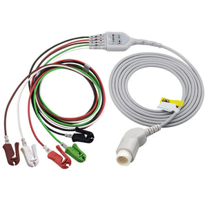
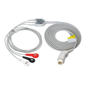
 Verifying ECG and respiration through the accessory chain with a multi-parameter simulator.
The following acceptance criteria are derived from manufacturer service guides (Philips IntelliVue Service Manual, GE CARESCAPE Service Manual, Mindray BeneVision Service Guide) and aligned with AAMI EQ89 (Guidance for the Use of Medical Equipment Maintenance Strategies) and IEC 60601-1 general safety requirements. These represent the standard tolerances used during PM for patient monitors from Philips, GE, Mindray, Dräger, and Nihon Kohden.
| Parameter | Test method | Acceptance criteria | Test equipment | Accessory under test |
|---|---|---|---|---|
| ECG / heart rate | Connect ECG simulator to monitor via cable + electrodes; set simulator to NSR 80 bpm | HR: ±2 bpm; clean waveform; no baseline artifact | Patient simulator (ECG output) | ECG cables + leadwires |
| Respiration (RESP) | Impedance-based via ECG leads; set simulator to 20 rpm | RESP: ±2 rpm | Patient simulator (RESP output) | Same ECG cable (RESP uses ECG leads RA–LL) |
| SpO2 | Connect SpO2 sensor to monitor; use SpO2 simulator or healthy finger | 95–100 % on a healthy finger; stable reading; no intermittent dropouts | SpO2 simulator (Pronk OxSim, Fluke SPOT Light) or healthy finger | SpO2 sensors + adapter cables |
| Temperature | Connect temp probe via adapter cable; use temp simulator set to 37 °C and 40 °C | Display: ±0.2 °C of simulator value; test both T1 and T2 channels | Temperature simulator or precision resistor (YSI 400 or 700 series-matched) | Temp probes + adapter cables |
| IBP | Connect transducer via IBP cable; zero open to atmosphere; apply 100 and 200 mmHg | Zero: ±1 mmHg; pressure: ±2 mmHg of reference; plus square-wave test (optimal damping) | Pressure simulator or calibrated manometer | IBP cables + transducers |
| NIBP | Connect cuff + hose; wrap on rigid cylinder; run built-in leak test | Leak test: <5 mmHg drift in 60 s; overpressure cutoff activates correctly (300 mmHg adult / 150 mmHg neonate) | Built-in leak-test mode; NIBP simulator (Pronk SimCube) | NIBP cuffs + hoses |
| EtCO2 | Connect sensor + sampling line; use CO₂ simulator or test gas (5 % CO₂ balance N₂) | Per manufacturer spec (typically ±2 mmHg or ±2 %) | CO₂ test gas or EtCO2 simulator | EtCO2 sensors + water traps + sampling lines |
🔄 Verified replacement accessories by parameter
Examples of MedLinket accessories designed to meet the acceptance criteria in the table above. All units undergo 100% factory testing against OEM monitor specifications before shipment.
ECG / Respiration (HR ±2 bpm · RESP ±2 rpm)
SpO2 (95–100% on a healthy finger)
Temperature (±0.2 °C · YSI 400/700 matched)
IBP (zero ±1 mmHg · pressure ±2 mmHg)
NIBP (leak <5 mmHg / 60s)
EtCO2 (±2 mmHg or ±2%)
Critical note: SpO2 technology matching
Matching SpO2 sensors by technology
Select replacements that match your monitor's SpO2 module to ensure valid verification results.
Not sure which technology your monitor uses? See the SpO2 connector pinout reference to identify by connector shape.
Temperature-probe verification also requires technology matching. YSI 400-series and YSI 700-series probes use different thermistor resistance curves and are electrically incompatible — inserting the wrong type into a monitor produces inaccurate readings or error codes. For a detailed comparison, see our YSI 400 vs. 700 temperature probe guide. If you are seeing temperature-probe errors during PM, our temperature-probe errors troubleshooting guide walks through each failure mode.
📄 Free download: calibration quick-reference card (PDF)
Post this at your calibration workstation. A one-page reference with acceptance criteria for all 6 parameters (ECG ±2 bpm, SpO2 95–100%, Temp ±0.2 °C, IBP zero ±1 mmHg, NIBP <5 mmHg drift), recommended verification intervals by care environment, an essential test-equipment list, and the critical SpO2 technology-matching warning.
⬇ Download PDF SpO2 verification with a technology-matched functional tester.
Recommended verification intervals
The following intervals synthesize manufacturer service-manual recommendations with AAMI EQ89 risk-based maintenance guidance and Joint Commission (TJC) survey expectations. Facilities should document their chosen intervals and rationale as part of their equipment-management program documentation.
| Test type | Recommended interval | Source / basis |
|---|---|---|
| Full PM (all parameters) | Annually; semi-annually for high-acuity areas (ICU, OR, NICU) | Manufacturer service manuals; TJC EC.02.04.03; AAMI EQ89 risk-based interval guidance |
| Electrical safety test (per IEC 62353) | At every PM and after every repair | IEC 62353 Clause 4 — recurrent testing shall include safety-analyzer measurements |
| Safety / functional check | Weekly minimum | Manufacturer guidelines for high-use clinical areas |
| Accessory inspection | At every PM + whenever a clinical complaint is received | IEC 62353 Clause 4.4 — visual inspection of accessories and applied parts |
| NIBP leak test | At every PM; additionally after any cuff or hose replacement | Manufacturer PM procedures; see NIBP measurement errors troubleshooting |
| IBP zeroing verification | At every PM; clinically: at every nursing handover, bed-height change, or transducer repositioning | Clinical best practice; see IBP transducer troubleshooting |
| Battery optimization | Every 3 months (full charge → full discharge → full recharge) | Manufacturer service manuals |
| Battery replacement | Lead-acid: 2 years; lithium-ion: 3 years (preventive replacement) | Manufacturer service manuals; cycle-count data |
Essential test equipment for accessory verification
| Equipment | Tests covered | Example products |
|---|---|---|
| Multi-parameter patient simulator | ECG (HR, arrhythmias), RESP, IBP, temperature | Fluke ProSim 4/8; Pronk SimSlim |
| SpO2 functional tester | SpO2 saturation, heart rate, perfusion index | Fluke SPOT Light; Pronk OxSim Flex |
| NIBP simulator | NIBP systolic/diastolic/MAP accuracy; leak test; overpressure test | Pronk SimCube SC-5; Fluke ProSim NIBP module |
| Electrical safety analyzer | Ground continuity, leakage current, insulation resistance (per IEC 62353) | Fluke ESA615/620; Rigel 288+ |
| Digital multimeter | Cable continuity, temperature-probe resistance, shield integrity | Any quality DMM with continuity and resistance modes |
| Temperature simulator / precision resistor | Temperature-probe verification at known test points (must match YSI 400 or 700 series) | FOGG TP400/700; precision-resistor decade box |
All test equipment must itself be calibrated and NIST-traceable (or equivalent national standards body per ISO/IEC 17025). Verify your simulators' calibration certificates are current before using them to test patient-monitoring equipment. Using an out-of-calibration simulator invalidates all test results and creates a compliance gap during TJC surveys.
The accessory's role in monitor PM
Accessories are tested as part of the monitor PM — not separately. During a complete PM cycle, the typical workflow (consistent with AAMI EQ89 and manufacturer service-manual structure) is:
- Visual inspection — monitor housing, display, ports, and all connected accessories (per IEC 62353 Clause 4.4).
- Electrical safety testing — ground continuity, leakage current (per IEC 62353 Clause 5).
- Parameter verification — ECG, SpO2, NIBP, Temp, IBP using simulators through the patient's accessory chain.
- Alarm testing — verify high/low alarm triggers at set limits.
- Battery test — capacity check; optimization if due.
- Documentation — record all results in the CMMS (see our documentation & compliance guide for specific fields to capture).
If a parameter fails during step 3, the BMET replaces the accessory with a known-good unit and retests. If the known-good accessory passes, the original accessory was the problem. If the known-good also fails, the monitor module is the problem. This swap-and-retest approach — documented in AAMI recommended practices and manufacturer troubleshooting guides — is the standard diagnostic method. For detailed error-code-based diagnosis, see our patient monitor error codes troubleshooting guide.
Accessories that pass verification during PM should be documented as verified, along with the serial number of the test equipment used. Per IEC 62353, this test documentation forms part of the medical device's lifetime record and must be retained for the duration specified by your facility's record-retention policy.
Need verified compatible accessories for your PM program?
MedLinket accessories are 100% factory-tested before shipment and designed to pass your PM verification criteria. ISO 13485-certified manufacturing (TÜV audited), FDA 510(k) cleared, CE marked, MDSAP certified. Compatible with Philips, GE, Mindray, Dräger, Nihon Kohden and other major monitor brands.
Applicable standards & references
The verification criteria and intervals in this guide are informed by the following standards. BMETs should maintain current copies of these documents as part of their department reference library.
| Standard | Title / relevance |
|---|---|
| IEC 62353:2014 (Ed. 2.0) | Medical Electrical Equipment — Recurrent Test and Test After Repair. Defines electrical-safety test procedures for in-service medical equipment, including leakage current, ground continuity, and functional testing of attached accessories. |
| IEC 60601-1:2005+AMD2:2020 | Medical Electrical Equipment — General Requirements for Basic Safety and Essential Performance. Establishes baseline safety and performance requirements referenced by manufacturer service manuals. |
| AAMI EQ89:2015 | Guidance for the Use of Medical Equipment Maintenance Strategies, Including Risk-Based Maintenance. Provides a framework for evidence-based PM intervals and risk classification. |
| ISO 13485:2016 | Medical Devices — Quality Management Systems. Governs manufacturing quality for accessories; MedLinket is ISO 13485 certified (TÜV Rheinland). |
| TJC EC.02.04.03 | Joint Commission standard requiring hospitals to maintain, test, and inspect medical equipment according to manufacturer instructions and risk-based strategies. |
| ISO/IEC 17025:2017 | General Requirements for the Competence of Testing and Calibration Laboratories. Governs test-equipment calibration traceability (NIST or equivalent). |
Frequently asked questions
Do patient monitor accessories need calibration?
Accessories need performance verification, not calibration. They have no adjustment mechanism — you cannot "calibrate" a cable or sensor in the field. During PM, you test the accessory + monitor chain against a simulator and verify readings are within specification (e.g., ECG ±2 bpm, NIBP leak <5 mmHg/60 s). If the accessory fails verification, you replace it. The monitor itself may have internal calibration routines managed through service mode — those are separate from accessory testing.
What are the acceptance criteria for ECG cable verification during PM?
Heart rate should read within ±2 bpm of the simulator setting. The ECG waveform should be clean with no baseline artifact, no excessive noise, and morphology matching the simulator output. Respiration (impedance-based via ECG leads RA–LL) should read within ±2 rpm. These are standard manufacturer service-guide criteria across Philips, GE, Mindray, and other brands. For ECG cable connector identification, see our ECG cable connector types guide.
How do I verify SpO2 accuracy without a dedicated simulator?
Use your own healthy finger as a basic functional test — the monitor should display 95–100 % with a stable reading and no intermittent dropouts. This confirms the sensor, cable, and module are all functional. However, a healthy finger cannot verify accuracy at lower saturation values. For precise accuracy verification, a dedicated SpO2 simulator matched to the monitor's SpO2 technology (Masimo, Nellcor OxiMax, Philips FAST, etc.) is required. Technology-specific connector details are covered in our SpO2 connector pinout reference.
How often should patient monitor accessories be tested?
At every scheduled PM (annual or semi-annual per AAMI EQ89 risk assessment), plus whenever a clinical complaint is received. Weekly safety and functional checks are recommended as a minimum for high-acuity areas. Accessory visual inspection for missing, non-functional, faulty, or damaged items should be part of every PM and every clinical-complaint response. Battery optimization should be performed every 3 months.
What happens if my test equipment is out of calibration?
Using an out-of-calibration simulator or safety analyzer invalidates all test results taken with that equipment. Per ISO/IEC 17025, test equipment must be NIST-traceable (or equivalent national standards body) with current calibration certificates. If a TJC surveyor finds expired calibration on your test equipment, all PM records based on those tools become suspect. Always verify your simulators' calibration status before beginning a PM cycle.
What is the difference between this calibration guide and the PM checklist?
This page focuses specifically on calibration verification — the acceptance criteria, procedures, test equipment, and standards that govern accuracy testing of each parameter. The PM checklist covers the entire PM workflow — visual inspection, electrical safety, parameter verification, alarm testing, battery checks, and documentation — of which calibration verification is one step. For documentation requirements specifically, see our compliance record-keeping guide.
Related BMET resources
About MedLinket
MedLinket (Shenzhen Med-link Electronics Tech Co., Ltd) — established 2004, 20+ years manufacturing compatible patient-monitoring accessories. Every MedLinket product is 100% factory-tested before shipment, designed to meet the verification criteria used during your PM program. The company holds 33 NMPA Class II registrations and is FDA 510(k) cleared, CE marked under MDR 2017/745, and certified to ISO 13485:2016 (TÜV Rheinland) and MDSAP, with additional registrations across MHRA, ANVISA, TGA and PMDA. Manufacturing runs across a dual self-owned base in Shenzhen (HQ) and Shaoguan, producing over 10,000 product types from more than 2,800 molds, and serving 2,000+ hospitals across 110+ countries. Product-liability insurance is carried up to US $5 million. (Monitor brand names are referenced for compatibility only and imply no OEM or endorsement relationship.)
Contact: shopify@medlinket.com | WhatsApp: +852 6467 3105 | 1-hour response
Part of MedLinket's BMET Resource Hub. By the MedLinket Clinical Engineering Team; reviewed by the MedLinket BMET Technical Advisory Board — June 2026.